Winding Resistance Testing Methods for Power Transformers
📌 Executive Summary
Detecting shorted turns, loose connections, and tap changer contact degradation through precise DC resistance measurements.
1. Principles of DC Winding Resistance Measurement
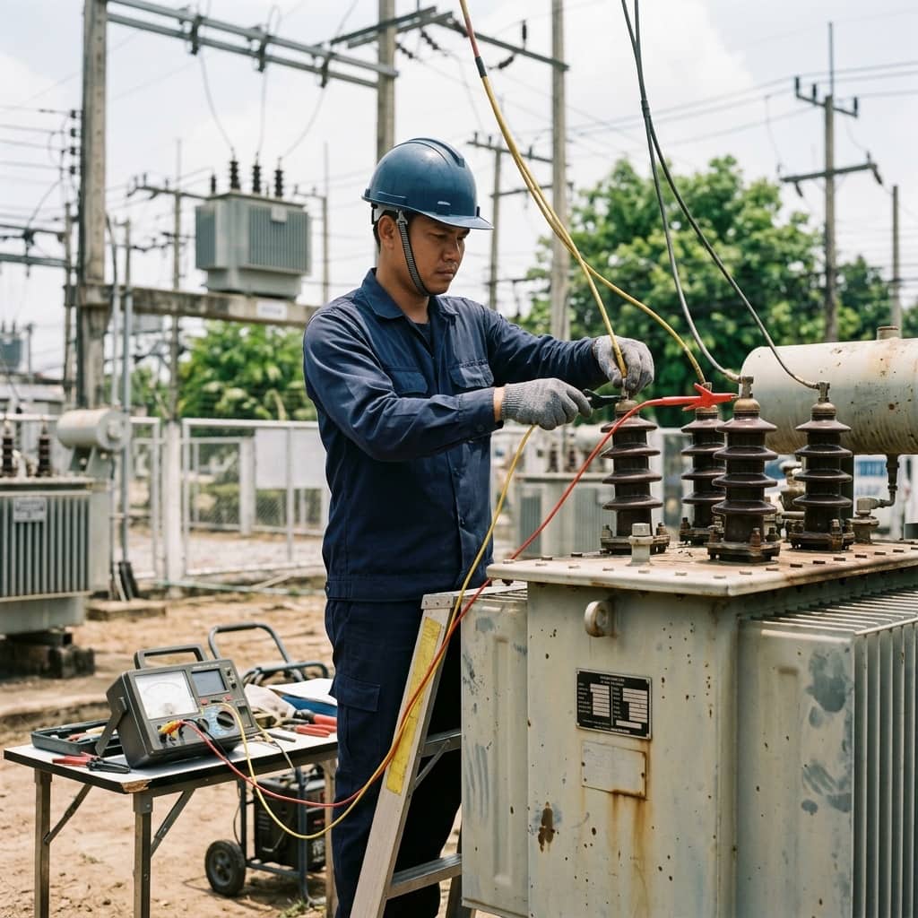
The winding resistance test measures the DC resistance of each phase winding at each tap position to detect conductor-path defects inside the transformer — loose joints, deteriorated brazed connections, broken strands, or eroded tap changer contacts. The principle is to inject a constant DC current through the winding, wait for the current to stabilize, then measure the voltage drop and compute resistance by Ohm's law.
The transformer-specific challenge is the very high inductance of the windings, especially low-voltage windings wound on the iron core. The DC source must saturate the core and the current must settle completely before readings are taken, otherwise values read high and drift. Modern test sets include circuits that drive the core into saturation faster, and — critically — a safe discharge circuit, because the energy stored in a large winding can generate lethal back-EMF if the circuit is opened abruptly.
2. Reference Standards and Acceptance Criteria
Winding resistance measurement is a routine test for every new transformer under IEC 60076-1 and one of the primary field diagnostics per IEEE C57.152 for in-service units. The widely used criterion is that the three phase resistances at the same tap should agree within roughly 2 percent of their average, and any comparison against the factory test report must first be corrected to a common temperature base.
Temperature correction is the most frequently skipped step. Copper resistance changes about 0.4 percent per degree Celsius, so a field measurement taken tens of degrees away from factory conditions will show apparent deviations that are purely thermal if left uncorrected. The correction formula uses the constant 235 for copper (225 for aluminium) as given in IEC 60076-1, and the winding or oil temperature at the time of measurement should be recorded with every result.
- IEC 60076-1: specified as a routine test for new transformers
- IEEE C57.152: field diagnostic testing guide
- Phase-to-phase deviation should stay within about 2% of the average
- Always temperature-correct before comparing with factory results (constant 235 for copper)
3. Safe Field Test Procedure
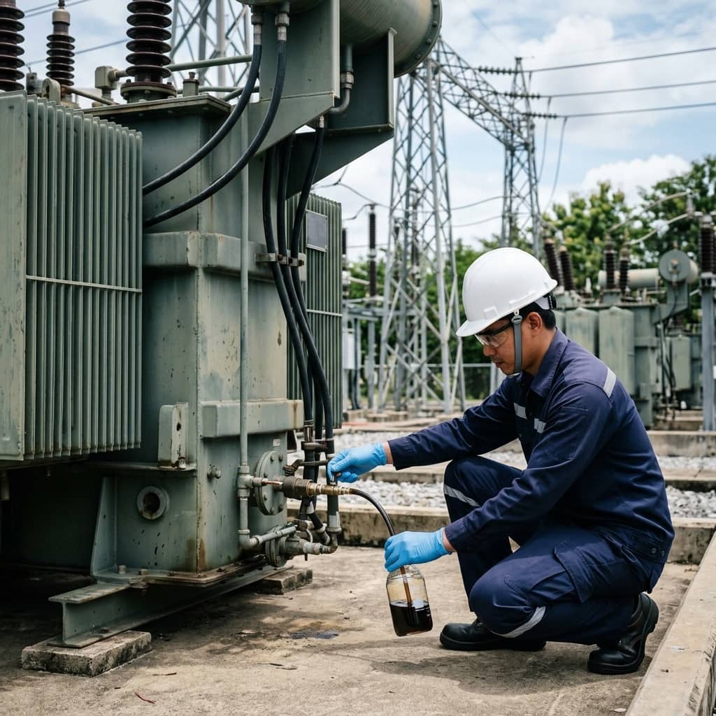
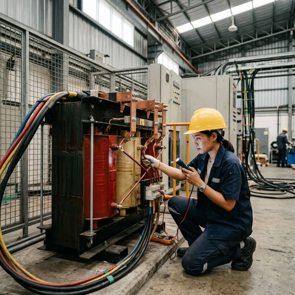
Before testing, isolate the transformer on both HV and LV sides, ground all terminals, allow discharge, then lift grounds only on the terminals under test following the test set's procedure. Measure every phase at every tap changer position — the most common weak point is the contact of rarely used tap positions, where oxide film builds up and produces abnormally high resistance.
During measurement, wait for a fully stable reading before recording; large transformers can take several minutes per point. After measuring, discharge through the test set's circuit until current reaches zero before disconnecting leads. An important caution: DC testing leaves residual magnetism in the core, which causes abnormally high inrush current at re-energization and disturbs other tests such as SFRA or exciting current. Demagnetization should therefore be performed as the final step every time.
4. Analyzing Common Abnormal Results
Common abnormal patterns have signatures that localize the problem. High resistance on one phase across all taps points to an internal joint or bushing terminal on that phase. High readings only at specific tap positions implicate those tap changer contacts directly. Unstable or jumping readings suggest a loose joint whose contact vibrates under current.
When an anomaly appears, do not immediately conclude the tank must be opened. Retest to confirm, and first check test lead tightness and external terminal cleanliness — dirty probe contact is the leading cause of erroneous readings. For oxide film on tap contacts, the first remedy is to exercise the tap changer through its full range several dozen times so the contacts self-clean, then remeasure; in many cases values return to normal without opening the tank. If the anomaly persists, supplement with DGA and dynamic resistance measurement before committing to a major repair.
Need engineering consultation regarding Transformer?
The WIN TECH SERVICE engineering team is ready to provide site surveys, electrical system inspections, and prepare accurate legal certification reports.