Protective Relay Coordination Study for High Voltage Networks
📌 Executive Summary
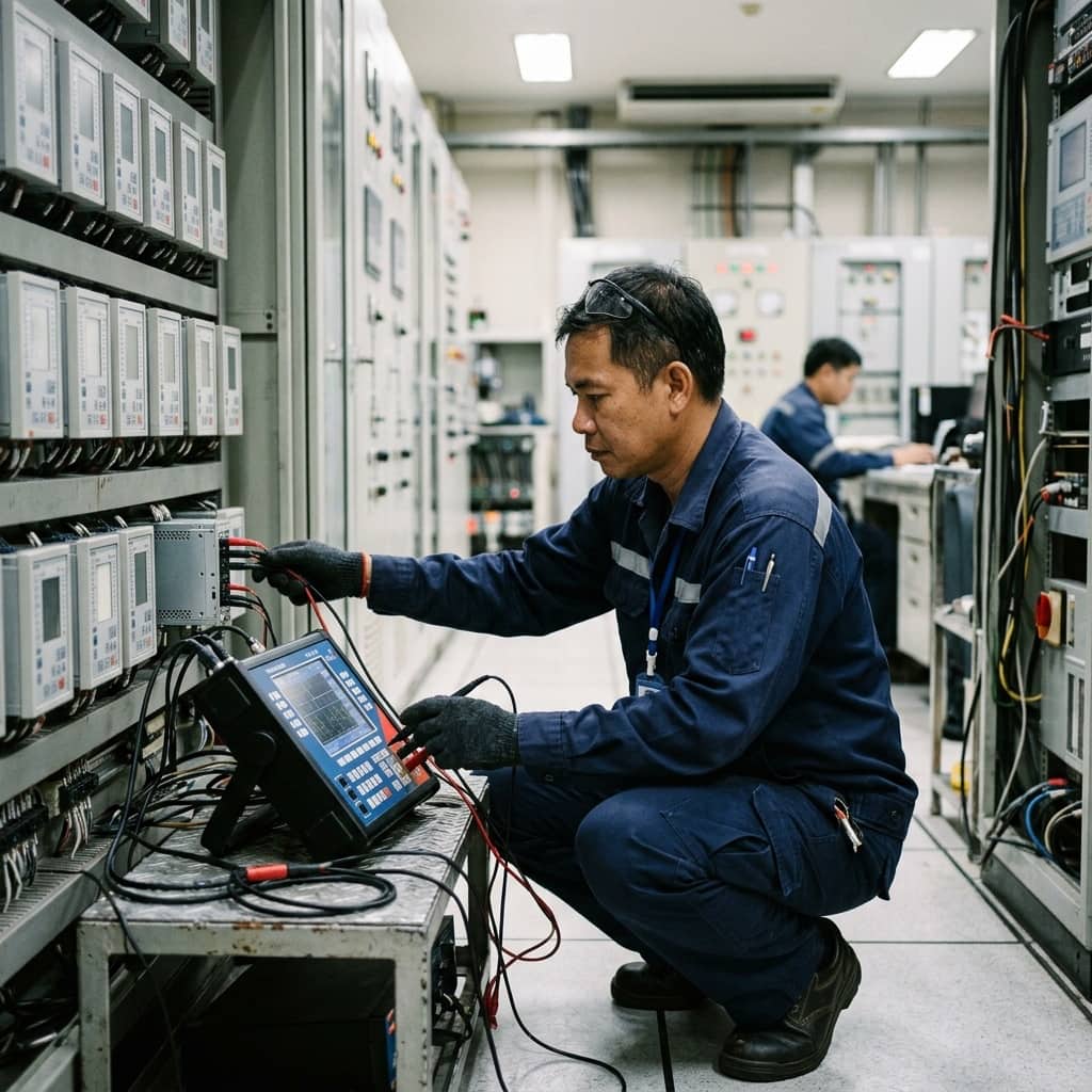
Setting overcurrent (50/51) and earth fault (50N/51N) curves to isolate electrical faults locally without tripping upstream feeders.
1. What Relay Coordination Is and Why It Matters
Protection coordination is the discipline of setting every relay and protective device in a system to operate hierarchically: the device nearest the fault must clear it first, while upstream devices serve as backup that acts only if the front line fails. This property, called selectivity, confines outages to the smallest possible area — instead of a single feeder fault blacking out an entire plant because the incoming breaker raced ahead and tripped first.
Systems that have never had a coordination study, or whose study predates later load growth and equipment changes, typically show the symptom of "plant-wide outages from minor faults" — or the reverse, relays that never operate until equipment is severely damaged. A coordination study is not a one-time exercise; it must be revisited whenever the system changes significantly, such as adding transformers, replacing breakers, or when the utility's upstream short-circuit levels change.
2. Core Protection Functions and Governing Standards
The foundation of industrial distribution protection is the overcurrent relay (ANSI 50/51): function 51 operates with an inverse time delay proportional to current magnitude, while 50 trips instantaneously above its threshold, paired with earth-fault functions (50N/51N) that detect ground faults at currents far below phase-fault levels. Standard inverse-time curves — Standard Inverse, Very Inverse, Extremely Inverse — are defined in IEC 60255, and device function numbers follow IEEE C37.2.
The key reference for coordination studies in industrial and commercial systems is IEEE 242 (the Buff Book), which explains selecting the coordination time interval between adjacent protection layers, allowing for breaker operating time, relay tolerance, and a safety margin combined. Settings must also be checked against transformer and cable damage curves so that equipment is genuinely protected — not merely coordinated.
- 50/51 — instantaneous and inverse-time overcurrent
- 50N/51N — low-current earth-fault detection
- IEC 60255 — standard inverse-time curve definitions
- IEEE 242 (Buff Book) — industrial coordination guide
- Always check settings against transformer and cable damage curves
3. A Systematic Coordination Study Workflow
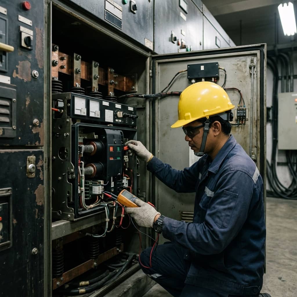
The study begins with complete, current system data: the single line diagram, transformer ratings and impedances, cable data, CT ratios, every relay's model and setting ranges, and the utility's short-circuit contribution at the intake. Fault currents are then calculated at every bus for both maximum and minimum conditions, because settings must operate dependably at the lowest fault current yet remain stable at maximum load including transformer and motor inrush.
Next, the time-current characteristic (TCC) curves of all protection layers are plotted on one graph, and pickup currents, time multipliers, and curve types are adjusted so each layer maintains a proper coordination interval across the credible fault current range. The approved setting schedule is then applied in the field, and each relay is proven by secondary injection testing to operate on its designed curve. The study closes with full documentation archived as the baseline for the next revision.
4. Common Problems and Long-Term Upkeep
Classic problems include settings inherited by habit without supporting calculation, pickups set so high they miss end-of-line faults, transformer inrush overlooked so the breaker trips on every energization, and new relays programmed by copying old settings without verifying the curve types truly match. Systems with parallel generators or solar also see fault levels shift with operating mode, which an older study may not cover.
Long-term upkeep means revising the study after every significant system change and at minimum on the maintenance policy's review cycle, performing periodic secondary injection tests to catch relay degradation, keeping a single approved settings document with no field changes outside engineering review, and analyzing every real trip event to confirm the operating sequence matched design — each real event being the best possible test of coordination quality.
- Never set relays by habit without calculation
- Always account for transformer and motor inrush
- Revise the study when the system changes or parallel sources are added
- Analyze the operating sequence after every real trip event
Need engineering consultation regarding High Voltage?
The WIN TECH SERVICE engineering team is ready to provide site surveys, electrical system inspections, and prepare accurate legal certification reports.