VLF Cable Testing & Partial Discharge Diagnostic on HV Cables
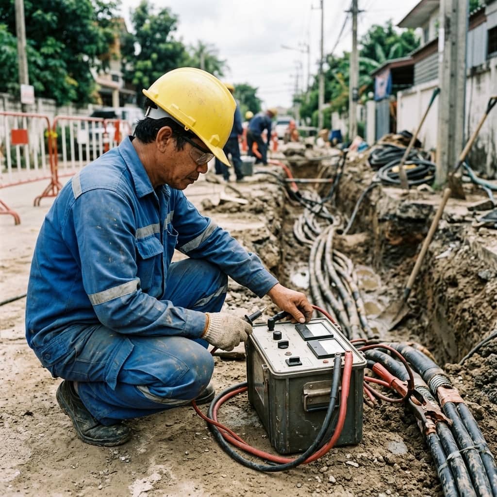
📌 Executive Summary
Why VLF 0.1Hz testing is superior to DC Hipot for XLPE insulated high voltage underground cables.
1. Why VLF Testing Replaced DC Hipot for HV Cables
XLPE-insulated underground cables are the arteries of modern high-voltage distribution, but their weak points are insulation defects — voids, installation cuts, and poorly made joints — which grow into water trees and electrical trees until the insulation punctures. High-voltage testing after installation and at maintenance intervals is essential to find these weaknesses before they cause an in-service failure.
Extensive research and field experience have shown that DC Hipot testing of XLPE can leave trapped space charge in the insulation; when AC service voltage is restored, this charge locally intensifies the electric field and accelerates failure. Very Low Frequency (VLF) AC testing at 0.1 Hz has therefore become the standard alternative, applying electrical stress representative of real operating conditions with test equipment compact enough to bring to site.
2. Test Standards and Voltage Levels
The governing standard for VLF testing is IEEE 400.2, which specifies test voltages as multiples of the phase-to-earth operating voltage (Uo), with higher levels for acceptance testing of new cables than for maintenance testing of aged ones, and typical energization times of 15–60 minutes. The overall framework for field testing of cable systems is IEEE 400, while factory cable testing follows the IEC 60502 series.
Before testing, confirm that the cable, joints, and terminations are rated for the test voltage, and select the appropriate mode. VLF withstand is a pass/fail test, whereas diagnostic measurements performed under VLF energization — tan delta and partial discharge mapping — provide quantitative insulation condition data that supports proactive cable replacement planning.
- IEEE 400.2 — the primary VLF testing standard
- Test voltage set as multiples of Uo for acceptance vs maintenance
- Typical test duration 15–60 minutes
- Tan delta and PD diagnostics can be combined with the VLF source
3. Field Procedure for VLF Testing
Begin by isolating the cable at both ends, earthing it to discharge stored energy, and barricading the remote end where test voltage will also appear. Clean the terminations to reduce surface leakage, then perform an insulation resistance measurement as a screening test — abnormally low readings should be investigated first, since there is little value in applying VLF voltage to a cable already showing severe damage.
Connect the VLF set to one conductor at a time with the remaining phases and shields earthed, raise voltage in steps to the standard-specified level, and hold for the full test duration while monitoring leakage current. If breakdown occurs, use a cable fault locator to pinpoint the failure for repair or re-jointing. After testing, always discharge through a discharge stick and leave the cable solidly earthed for an appropriate period before anyone touches it.
4. Common Pitfalls and Precautions
A frequent mistake is failing to control the remote cable end, which may be in another building or substation, exposing bystanders to test voltage. Another is testing a cable longer than the VLF set can drive: cable capacitance grows with length, and the set may silently fail to reach the specified voltage. Always check the instrument's capacitive load rating against the cable length beforehand.
Be cautious about interpreting a withstand result alone — a cable that "passes" may still contain developing defects. Trending tan delta values across successive test campaigns reveals degradation before it becomes critical. For aged cables near end of life, discuss risk with the system owner before choosing the test level, because the purpose of testing is to make existing weaknesses fail at a controlled time rather than during live operation.
- Always secure the remote cable end
- Verify VLF capacitive load rating against cable length
- Trend tan delta at every test campaign
- Discharge and earth the cable before touching it
Need engineering consultation regarding High Voltage?
The WIN TECH SERVICE engineering team is ready to provide site surveys, electrical system inspections, and prepare accurate legal certification reports.