Fall-of-Potential Method for Substation Grounding Grid Resistance Testing
📌 Executive Summary
Accurate 3-pole and 4-pole ground resistance measurement procedures ensuring substation earth resistance <= 5 Ohms (or <= 1 Ohm for substations).
1. The Role of the Grounding System and Why It Must Be Tested
A grounding system performs three jobs at once: providing a return path so protective devices clear faults quickly, limiting touch and step voltages to levels safe for people, and dissipating lightning and surge currents into the earth. All of this depends on the system's earth resistance, which is not constant over time — ground rods and buried conductors corrode, joints degrade, and soil resistivity varies with season and moisture.
The commonly referenced value for Thai industrial facilities is an earth resistance not exceeding 5 ohms for general systems, while high-voltage substations require far lower values, generally targeting below 1 ohm, because their much larger fault currents create a more dangerous ground potential rise. Periodic re-testing is the only way to confirm that a buried, invisible system still performs as designed.
2. The Fall-of-Potential Method per IEEE 81
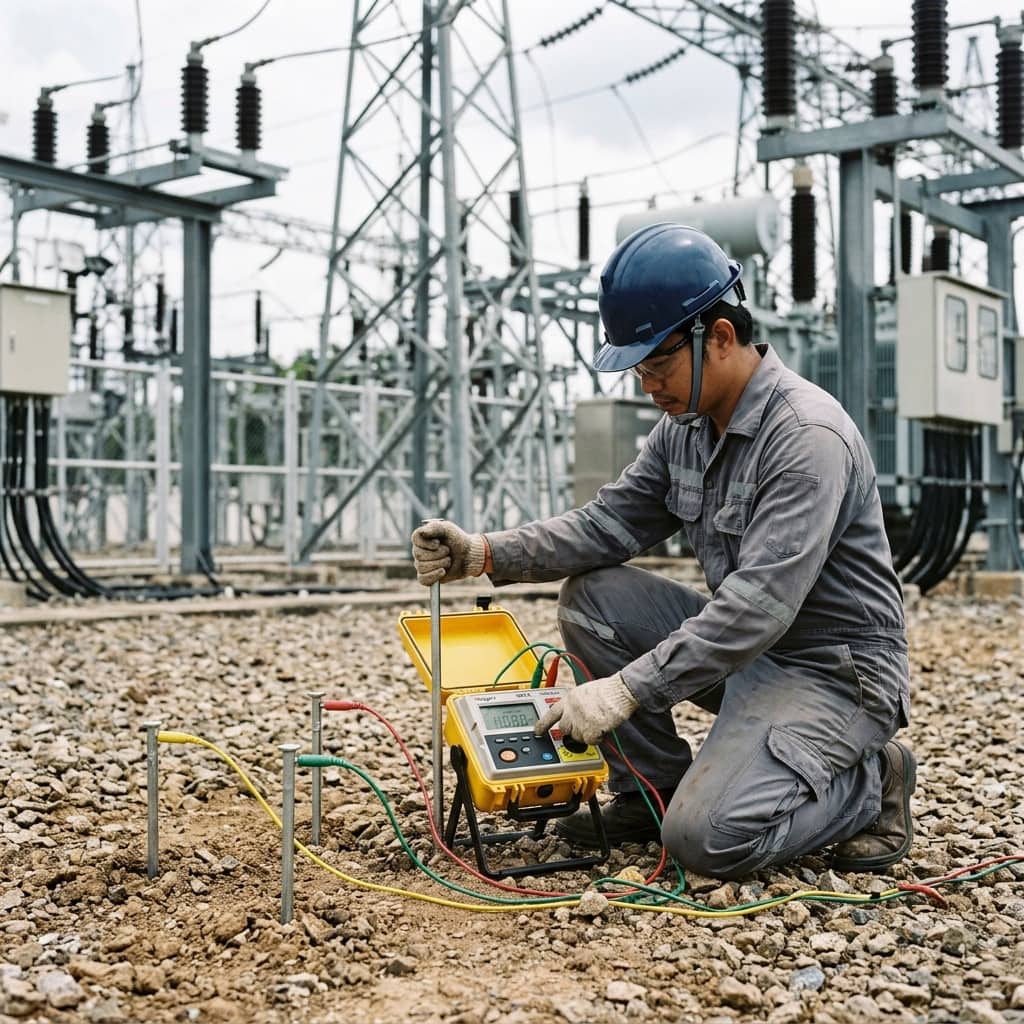
The fall-of-potential method per IEEE 81 places two test probes away from the grounding system under test: a current probe (C) at the far end and a potential probe (P) in between. The instrument circulates a test current at a distinctive frequency between the ground system and probe C, measures the voltage between the ground system and probe P, and computes resistance by Ohm's law. Probe P is moved through multiple positions along a straight line and resistance plotted against distance.
A valid measurement shows a plateau in the middle of the curve, and the plateau value is the true resistance. The well-known 61.8% rule states that in uniform soil the reading with P at 61.8% of the distance to C gives the correct value. The critical condition is that probe C be far enough away — commonly at least four to five times the diagonal dimension of the ground grid. If it is too close, the resistance zones of grid and probe overlap, the curve shows no plateau, and the result cannot be trusted.
- Place probe C at least 4-5 times the grid diagonal away
- Move probe P through multiple positions and plot the curve to find the plateau
- Use the 61.8% rule as a validity check in uniform soil
- Isolate the ground system from the utility neutral before measuring (only where safe and authorized)
- Record season and soil moisture conditions with every result
3. Field Techniques and Alternative Methods
The most common field constraint is insufficient space to place probes at theoretical distances, especially in industrial estates surrounded by concrete and buried utilities. Alternatives include the slope method, which mathematically compensates for limited spacing, and clamp-on ground testers, which measure inductively through a clamped loop without disconnecting anything or driving probes. The clamp-on method is convenient but valid only where multiple parallel ground paths exist, and it measures the loop resistance, not the isolated grid.
Measurements in energized substations must contend with 50 Hz stray current noise in the soil, which is why quality instruments test at an off-power frequency such as 128 Hz with filtering. It is also good practice to measure soil resistivity with the Wenner 4-pole method for design and analysis data, and to verify continuity between key grounding connections across the station with a micro-ohmmeter, confirming that every piece of equipment is still genuinely bonded to the grid.
4. Causes of High Earth Resistance and Improvement Options
When measured resistance exceeds limits, check the system's own integrity first: corroded or detached buried joints, conductors severed by later excavation work, and rods corroded beyond usefulness — more common in older plants than expected. Only then consider the soil itself: sandy or lateritic soils with high resistivity, or surface layers drying out in the dry season, which makes dry-season readings significantly higher than wet-season ones.
Improvement options, from basic upward: repair joints and replace corroded rods; add rods spaced at least one rod-length apart to reduce overlap effects; drive rods deeper to reach permanently moist strata; apply ground enhancement material such as bentonite around rods in high-resistivity soil; or extend the grid with additional horizontal buried conductors. Testing should be scheduled in the dry season — the worst case — to ensure the system passes year-round.
Need engineering consultation regarding Preventive Maintenance?
The WIN TECH SERVICE engineering team is ready to provide site surveys, electrical system inspections, and prepare accurate legal certification reports.