Exothermic Welding (Cadweld) Best Practices for Grounding Conductors
📌 Executive Summary
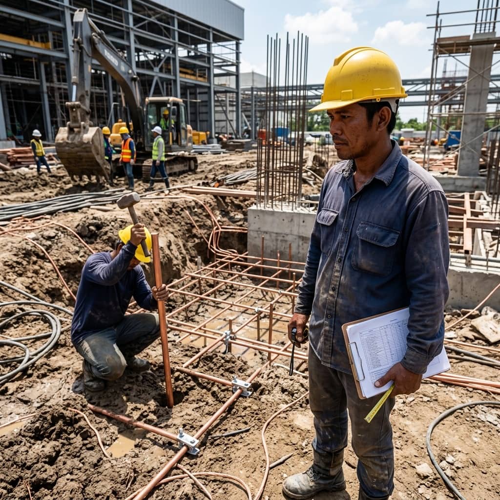
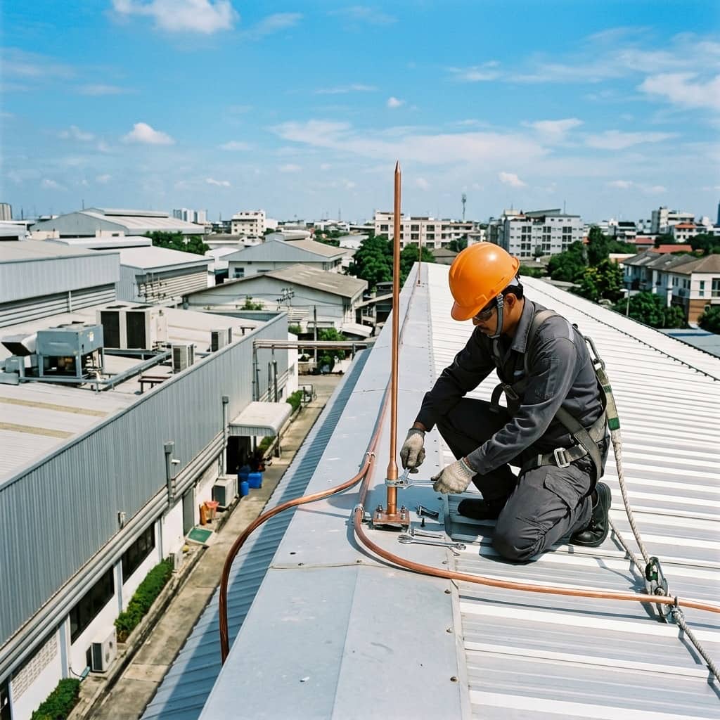
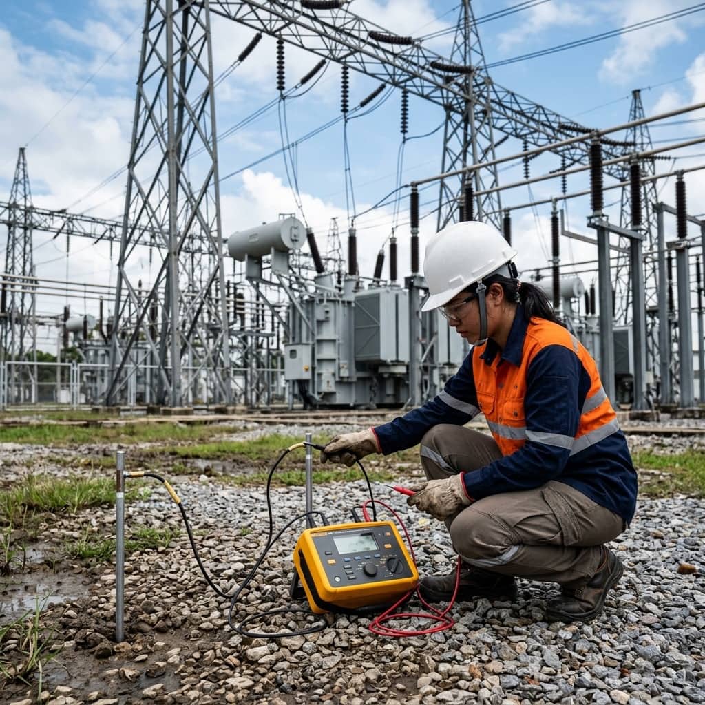
Preparing graphite molds, copper tape/cable surfaces, ignition powder, and inspecting molecular bond joint conductivity.
1. Why Buried Grounding Joints Should Be Exothermically Welded
Connections are the weakest points of any grounding system. Mechanical bolted or clamped joints buried in soil face moisture, oxygen, and mineral salts; oxide films form on the contact surfaces and thermal cycling loosens the clamping force, so joint resistance climbs steadily with no visible sign at the surface. Exothermic welding — widely known by the trade name Cadweld — solves this by fusing the copper into a molecular bond: the resulting joint has a current-carrying cross-section at least equal to the conductor, cannot loosen, and does not degrade through contact corrosion.
The process uses a thermite reaction between aluminum powder and copper oxide, generating enough heat to produce molten copper that flows into the weld cavity of a graphite mold and fuses the conductor ends together within seconds. This is why substation grounding specifications and any application where joints must survive high fault currents commonly require every buried connection to be exothermically welded or to be a corrosion-resistant connector qualified under IEEE 837, the standard for permanent connections used in substation grounding.
2. Work Preparation: Selecting Molds and Weld Metal
Weld quality is decided largely by preparation. The graphite mold must match both the joint configuration — straight splice, tee, cross, cable-to-ground-rod, or cable-to-structural-steel — and the exact conductor sizes on each side. The weld metal cartridge size must be the one the manufacturer specifies for that mold; the wrong charge produces an underfilled or incompletely fused joint. Conductor ends must be cut clean and wire-brushed to a bright finish, free of oxide, oil, and insulation residue.
Moisture is the number one enemy of this process: water contacting molten copper flashes to steam instantly and ejects molten metal from the mold — an extremely dangerous event known as spitting. Both mold and conductors must be completely dry; a new or cold mold must be preheated with a torch to drive off moisture before the first weld, and welding must never proceed in rain or in a flooded trench without protection. The mold should also be inspected before every shot: chipped, cracked, or over-used molds beyond the manufacturer's recommended weld count produce malformed joints with voids.
- Match the mold to both the joint configuration and the conductor sizes on each side
- Use only the weld metal cartridge size the manufacturer specifies for that mold
- Wire-brush conductors to a bright finish, free of oxide and oil film
- Preheat the mold to drive off moisture before the first weld; never weld wet
- Inspect the mold every shot; retire it when chipped, cracked, or past its rated weld count
3. Welding Procedure and Safety During the Work
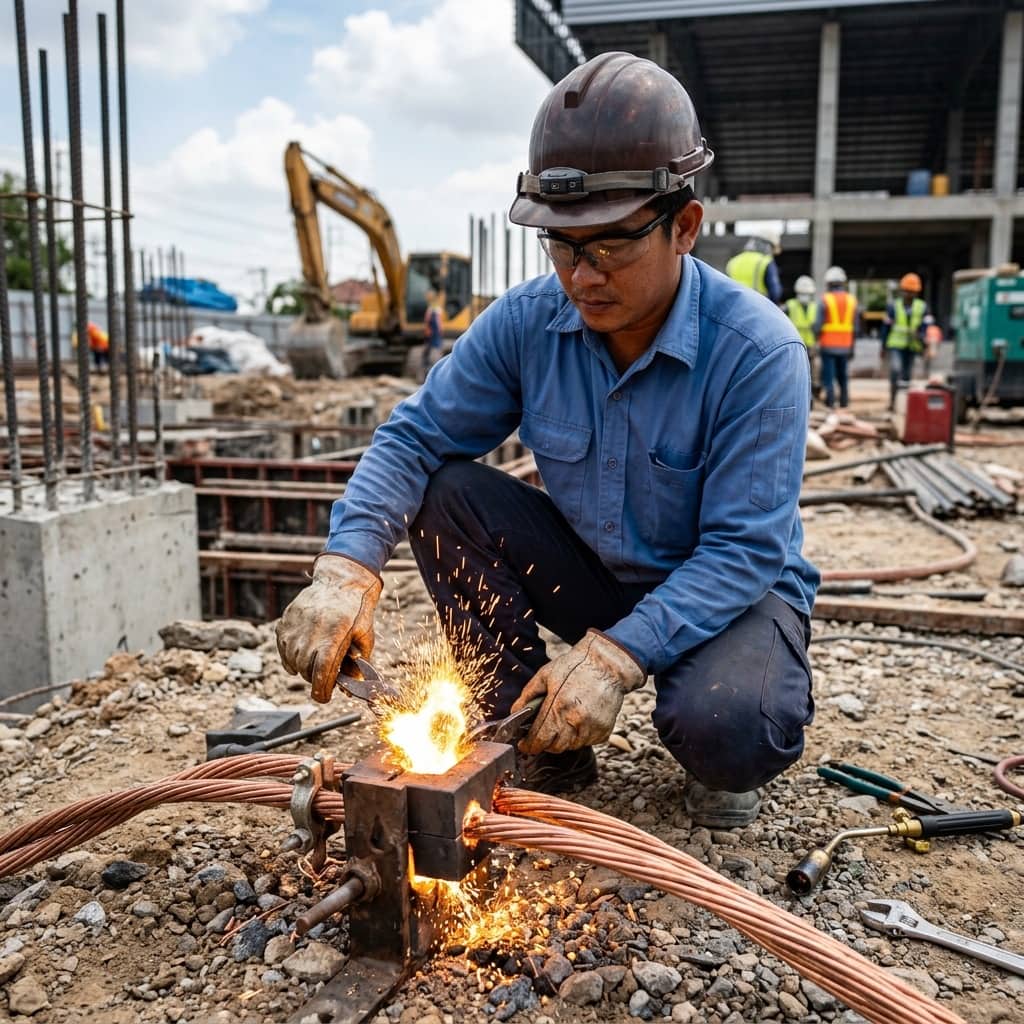
The welding sequence: position the conductors in the mold against the alignment marks so the ends meet at the center of the weld cavity, close the mold tightly with its handle clamp, place the steel retaining disk at the bottom of the crucible, pour in the weld metal, sprinkle the starting powder at the rim, close the lid, and ignite from the side with a flint igniter — or use a remote electronic ignition system on newer product lines, which is safer. After the reaction, allow the metal to solidify for the specified time before opening the mold, then chip away the slag and clean the mold with the supplied tools before the next weld.
For safety, the operator wears safety glasses or a face shield, leather gloves, and long sleeves, stands offset to the side rather than leaning over the mold during ignition, keeps others clear of the work radius, and ensures no flammable material is nearby. Weld metal cartridges are stored sealed, away from heat and moisture. Quality acceptance is visual — a completely filled cavity, a uniform surface, no porosity or voids — supported by a light hammer tap test and, on stringent projects, joint resistance measurement with a micro-ohmmeter.
4. Common Weld Defects and Quality Control
Most defective welds trace back to preparation: porous welds from mold moisture or degraded weld metal, underfilled welds from a wrong cartridge size or metal leaking from an improperly closed mold, cold joints from dirty or wet conductors, and off-center conductor placement leaving the joint cross-section thinner than specified. Such joints may survive normal service yet fail instantly when called upon to carry a large fault current — the very duty they exist for.
Sound quality control therefore includes operator training and qualification before production work, a weld log recording location, date, welder, mold model, and cartridge size for every joint, photographs of each weld before backfilling so supervisors can review them afterward, and random excavation inspections combined with overall system resistance measurement against design values. These practices keep a buried grounding system traceable for the entire life of the project.
Need engineering consultation regarding Safety & Grounding?
The WIN TECH SERVICE engineering team is ready to provide site surveys, electrical system inspections, and prepare accurate legal certification reports.