Substation Step and Touch Potential Safety Calculations (IEEE 80 Standard)
📌 Executive Summary
Calculating safe limits for body current, surface crushed rock layer resistivity, and ground grid conductor spacing.
1. The Hazard of Step and Touch Voltages in Substations
During a ground fault in a high-voltage substation, fault current of several kiloamperes flows into the ground grid and disperses into the surrounding soil, raising the surface potential unevenly across the site. This creates step voltage between a person's two feet and touch voltage between a hand contacting metal structure and the feet on the ground. These voltages drive current through the human body; beyond the threshold the heart can withstand, ventricular fibrillation can occur and cause death in under a second.
IEEE Std 80, the IEEE Guide for Safety in AC Substation Grounding, is the internationally used framework for computing safe voltage limits, accounting for the assumed body weight (50 kg or 70 kg criteria), the duration of fault current flow before protection clears, and the resistivity of the surface material layer. The governing principle is that the actual mesh touch voltage and step voltage produced by the grid design must remain below the tolerable body limits at every location inside and just outside the substation fence.
2. Design Parameters Under IEEE 80
Calculation begins with soil resistivity surveys using the Wenner four-pin method along multiple traverses and spacings to build a two-layer soil model. The maximum grid current is then derived by applying the current split factor and the decrement factor — which accounts for the DC offset component — to the symmetrical fault current. From there, the mesh voltage and step voltage are computed from the grid geometry, burial depth, conductor sizing, and the number of ground rods.
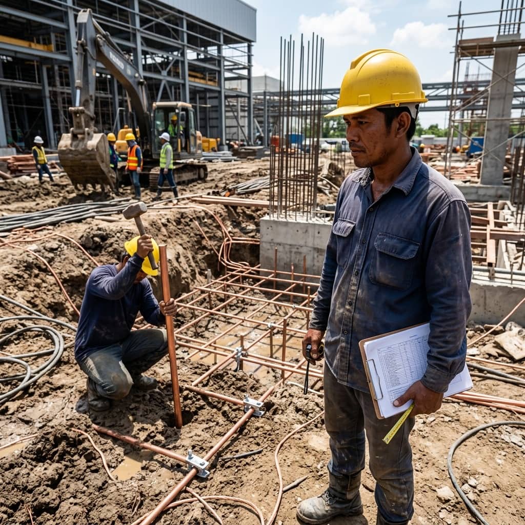
The crushed rock surface layer, typically 10-15 cm thick, plays a major role: its high resistivity increases the foot-to-ground contact resistance, significantly raising the tolerable voltage limits through the surface layer derating factor (Cs). The grid conductor cross-section must additionally be verified for thermal withstand of the fault current over the clearing time, with a corrosion allowance for the substation's full service life.
- Survey soil resistivity with the Wenner method on multiple traverses to build a two-layer model
- Derive maximum grid current using the split factor and decrement factor
- Compare computed mesh and step voltages against tolerable body limits
- Use a 10-15 cm crushed rock layer to raise the safe voltage thresholds
- Verify conductor thermal sizing against the protection clearing time
3. Field Testing to Validate the Design
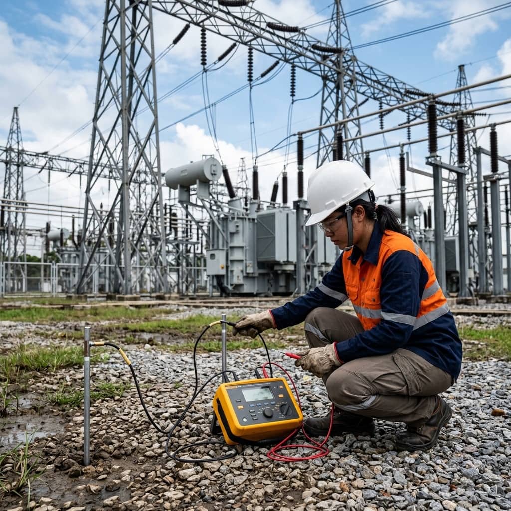
Once the grid is constructed, testing must confirm that reality matches the calculation. The standard approach is grid impedance measurement using a long-distance fall-of-potential traverse, extended to several times the grid diagonal so the test leads exit the influence zone of the large electrode. Actual touch and step voltages are then verified with a current injection test between the grid and a remote electrode, measuring voltages at high-risk points — steel structures, fence gates, substation corners — and scaling the readings up to the real fault current level.
Special attention belongs to the perimeter fence, which the public can touch while standing on soil outside the grid area, and to metallic pipes, cable trays, or rail lines crossing the fence line that can carry transferred potential beyond the station. All test results should be compiled into a baseline report for comparison during periodic re-testing over the substation's life.
4. Degradation Factors and Ongoing Surveillance
A ground grid degrades invisibly beneath the surface. Principal causes include corrosion of copper conductors or joints in acidic soils or under stray currents from nearby cathodic protection systems, civil excavation work inside the station that unknowingly severs conductors, and station expansions that raise fault current beyond the original design basis. The crushed rock layer also becomes contaminated over the years with soil and vegetation, losing the insulating surface property it had when new.
Sound surveillance practice includes periodic grid impedance re-testing — and re-testing after every system expansion — compared against the original baseline, random excavation inspection of buried joints, maintaining the crushed rock layer clean and at design thickness, and re-running the IEEE 80 calculations whenever system short-circuit levels increase due to added transformers or network interconnections. A design that was safe in the past may no longer be safe once the surrounding power system has changed.
Need engineering consultation regarding Safety & Grounding?
The WIN TECH SERVICE engineering team is ready to provide site surveys, electrical system inspections, and prepare accurate legal certification reports.