Industrial Earthing System Design: TN-S, TN-C-S, and TT Configurations
📌 Executive Summary
Evaluating fault loop impedance, touch voltage, step voltage, and protective bonding conductors for personnel safety.
1. Principles of Selecting TN-S, TN-C-S, and TT Earthing Configurations
The earthing system is the heart of electrical safety in an industrial plant, because it forms the path through which earth fault current returns to the source. Choosing between TN-S, TN-C-S, and TT configurations directly affects the fault loop impedance, the magnitude of prospective fault current, and the disconnection time of protective devices. In a TN-S system, the neutral (N) and protective earth (PE) conductors are separated throughout the installation, so no load current flows in the PE conductor — making it well suited to plants with large numbers of electronic devices and control systems.
A TN-C-S system combines N and PE into a single PEN conductor from the transformer to the main switchboard, where they are then separated. This saves conductor material on long feeders, but a broken PEN conductor is a serious hazard: exposed metalwork can immediately rise to a dangerous voltage relative to earth. A TT system instead relies on the consumer's own earth electrode, separate from the source electrode, which results in low fault currents and makes residual current devices (RCDs) the primary means of protection. The choice must therefore weigh load characteristics, feeder distances, and the earth electrode quality achievable on site.
2. Requirements Under EIT (Thai) Standards and IEC 60364
The Thai electrical installation standard published by the Engineering Institute of Thailand (EIT), which follows the framework of IEC 60364, sets the key rules for earthing systems: the sizing of grounding electrode conductors, the sizing of equipment grounding conductors relative to phase conductor size or overcurrent device rating, and the bonding requirements for exposed conductive parts. The core principle is that under an earth fault, the protective device must disconnect within a specified time so that the touch voltage never exceeds levels dangerous to the human body.
In practice, the engineer must verify that the measured fault loop impedance Zs satisfies the condition Zs × Ia ≤ U0, where Ia is the current that causes the protective device to operate within the required time and U0 is the nominal voltage to earth. If the condition fails, remedies include enlarging the protective conductor, shortening the circuit, or adding an RCD. The standards also specify earth electrode resistance targets for low-voltage systems and the conditions for separating or combining the lightning protection earth with the power system earth — both must be designed coherently for the whole building.
- Verify the disconnection condition Zs × Ia ≤ U0 on every significant final circuit
- Size equipment grounding conductors against the overcurrent device rating per the standard tables
- Bond exposed conductive parts and extraneous conductive parts into one system
- TT systems must always use RCDs as the primary protective device
- Coordinate the earth electrode design with the building lightning protection system
3. Site Measurement and Testing Procedures for Earthing Systems
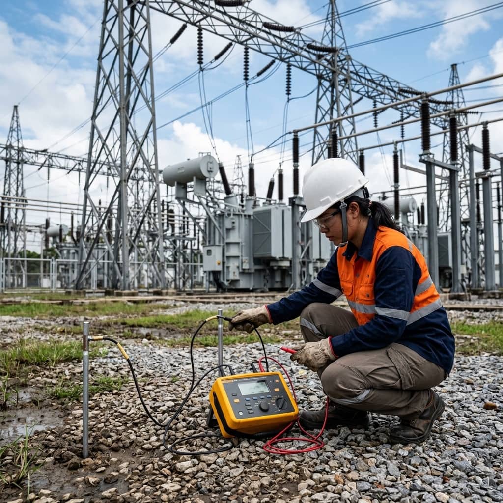
Earthing verification starts with electrode resistance measurement using the fall-of-potential (3-pole) method, placing the current and potential test stakes at correct proportional distances — the potential stake typically at about 62% of the current stake distance — so the reading lies outside the electrode's sphere of influence. Where electrodes are interconnected into a large system that cannot be isolated, a clamp-on earth tester or the selective measurement method with a current clamp can be used instead.
The next steps are measuring the earth fault loop impedance at final outlets to confirm protective devices will disconnect in time, continuity testing of protective conductors with a standardized test current, and functional testing of RCDs at both rated residual current and five times rating. All results should be recorded against design values and repeated annually — particularly in the dry season, when soil resistivity typically rises significantly and electrode resistance can drift out of specification.
4. Common Problems and Preventive Measures
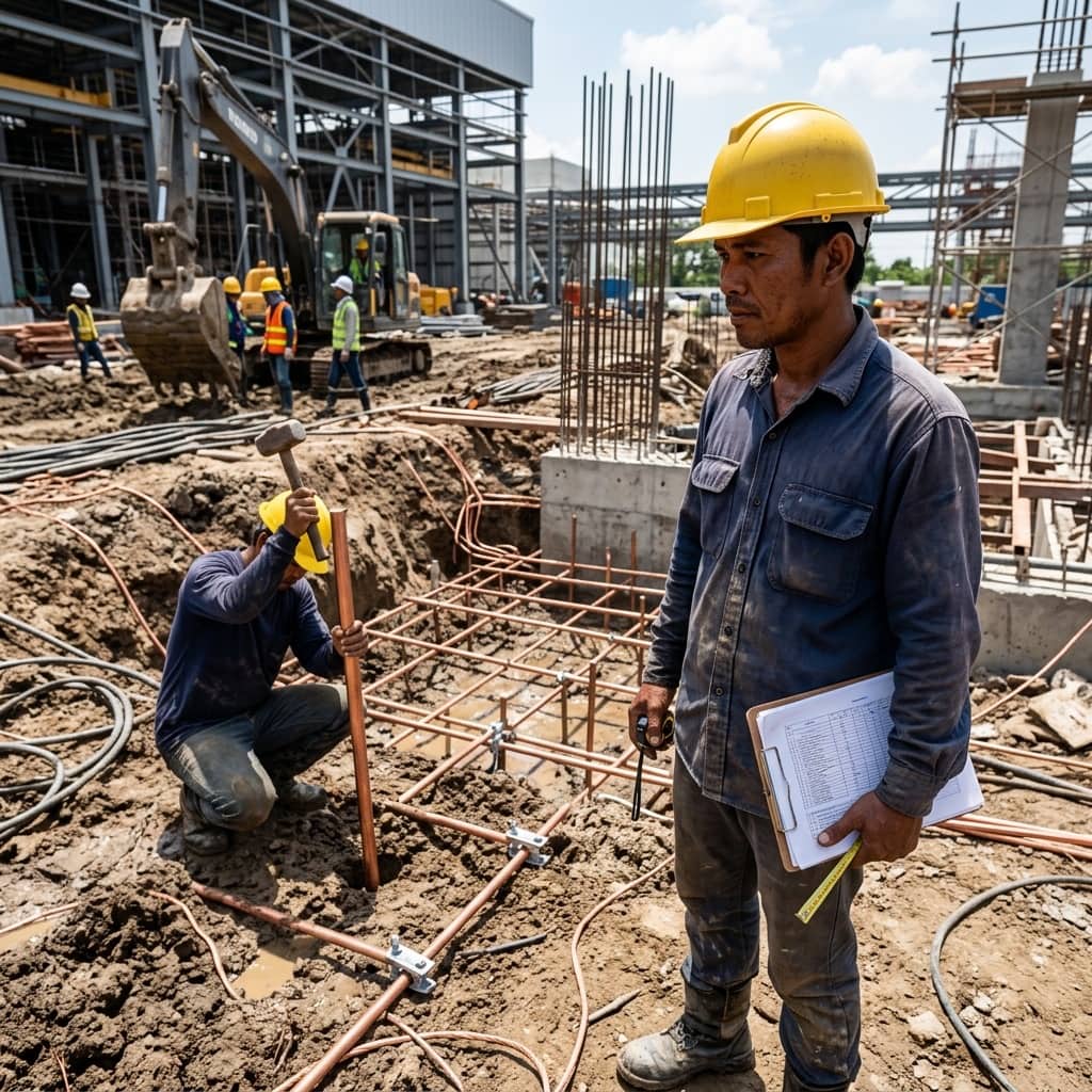
The most common problem found in plants is repeated neutral-to-earth bonding at multiple points downstream of the main switchboard. This diverts part of the load current into PE conductors and cable tray metalwork, injects noise into instrumentation systems, and can cause nuisance RCD tripping. Another frequent issue is loosened or corroded grounding connections over time — especially buried bolted joints that were not exothermically welded — which silently raises the overall system resistance.
Prevention starts with enforcing a single N-PE bond at the main switchboard as a correct TN-C-S design requires, keeping the grounding single-line diagram up to date, and building electrode resistance measurement, thermographic inspection of main ground connections, and RCD testing into the annual preventive maintenance plan. Re-verification should also follow every plant extension or machine relocation, because modifications made by contractors who do not understand the original TN-S architecture are a leading root cause of defects discovered later.
Need engineering consultation regarding Safety & Grounding?
The WIN TECH SERVICE engineering team is ready to provide site surveys, electrical system inspections, and prepare accurate legal certification reports.