Air Circuit Breaker (ACB) Contact Overhaul & Microprocessor Trip Unit Testing
📌 Executive Summary
Testing Long Time (L), Short Time (S), Instantaneous (I), and Ground Fault (G) protection curves using secondary injection kits.
1. The Role of the ACB and Why Overhauls Are Necessary
The Air Circuit Breaker (ACB) is the main breaker of the MDB, tasked with interrupting short-circuit currents of tens of kiloamperes by extinguishing the arc in air through its arc chutes. Its internals include energy-storage springs, main contacts, arcing contacts, and an electronic trip unit. As the last line of defence for the entire low-voltage system, a sticky mechanism or degraded contacts that slow or block operation will let damage cascade through the whole installation.
Years of continuous service dry out and harden the mechanism grease, fatigue the springs, and erode the contacts with each accumulated interruption. Most manufacturers therefore prescribe a full overhaul at intervals defined by service years or operation counts in the maintenance manual, covering strip-down cleaning, re-greasing with the specified lubricant, contact resistance measurement, and verification that the trip unit follows its configured protection curves.
2. Contact and Mechanism Inspection Criteria
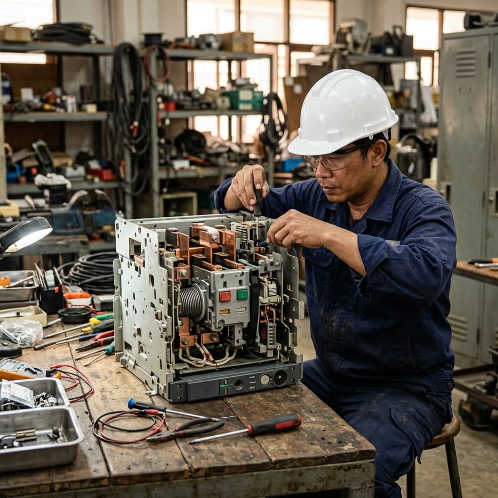
The heart of the overhaul is contact assessment. Arcing contacts, designed to make first and break last, wear faster than the main contacts. The technician measures the remaining thickness against the manufacturer's minimum, inspects the silver-alloy surfaces for melt marks, and measures contact resistance with a micro-ohmmeter injecting at least 100 A DC (DLRO). Phase readings should be closely matched and within the manual's limit; an abnormally high phase indicates insufficient contact pressure or degraded contact surfaces.
Mechanically, the charging spring assembly must complete full close-open cycles in both manual and motor modes; the emergency trip button and release coils (shunt trip, undervoltage release) are exercised; contact opening and closing times are measured where timing equipment is available; and the arc chutes are checked for cracked or soot-clogged splitter plates. Finally, cable and busbar connections are re-torqued to the manufacturer's specified values.
- Measure contact resistance with a DLRO and compare all three phases for balance
- Check arcing contact thickness against the manufacturer's minimum
- Exercise every shunt trip and undervoltage release coil
- Clean and inspect the splitter plates in each arc chute
- Re-grease only the points specified, using the manufacturer's designated grease
3. LSIG Trip Unit Testing by Secondary Injection
Modern microprocessor trip units provide four core protection functions collectively called LSIG: Long Time (L) for overload with an inverse-time curve, Short Time (S) for delayed short-circuit tripping to coordinate with downstream breakers, Instantaneous (I) for immediate clearing at the set threshold, and Ground Fault (G) for earth leakage detection. Secondary injection testing feeds simulated signals directly into the trip unit's test port to prove the electronics measure and trip exactly per the configured settings.
The procedure starts by recording every current setting (Ir, tr, Isd, tsd, Ii, Ig, tg), connecting the test set through the trip unit's test port, then injecting each function at several current multiples — for example 1.5 and 3 times Ir to verify trip times against the curve. Results are compared with the manufacturer's tolerance tables. Where a primary injection set is available, at least one phase should also be verified through the real current path, since secondary injection cannot reveal faults in the internal CTs and measuring circuits.
4. Frequent Field Findings
Common findings include hardened legacy grease slowing the opening mechanism beyond limits, one phase showing abnormally high contact resistance due to fatigued contact-pressure springs, burnt undervoltage release coils from chronically low control voltage, and ground-fault settings raised or disabled without any review of the coordination study. Using the wrong grease type is also seen, reacting with the original lubricant into a sticky compound.
Prevention means following the manufacturer's overhaul intervals strictly, logging every measurement in the breaker's history register for trend analysis, exercising continuously loaded breakers with at least one open-close cycle per year to prevent mechanism seizure, and re-validating LSIG settings against the latest protection coordination study whenever loads change or downstream breakers are added.
- Overhaul at the manufacturer's specified interval or operation count
- Log every measurement for degradation trend analysis
- Exercise continuously loaded breakers at least once a year
- Re-validate LSIG settings whenever the system or loads change
Need engineering consultation regarding Low Voltage & MDB?
The WIN TECH SERVICE engineering team is ready to provide site surveys, electrical system inspections, and prepare accurate legal certification reports.