Automatic Transfer Switch (ATS) Sequence & Emergency Generator Interlock Test
📌 Executive Summary
Verifying mechanical interlocks, mains failure sensing delay, generator start command, and transfer timing under load.
1. How an ATS Works with the Standby Generator
The Automatic Transfer Switch (ATS) monitors voltage and frequency of the utility supply. When it detects an outage, undervoltage, or phase loss persisting beyond the configured thresholds and delay, it commands the standby generator to start, waits until generator voltage and frequency stabilise within limits, then transfers the load from utility to generator. Once the utility returns and remains healthy through the confirmation timer, the ATS retransfers the load and lets the engine run a cool-down period before automatic shutdown.
The indispensable safety element is the interlock system — both mechanical and electrical — guaranteeing the two sources can never feed the load simultaneously. Paralleling unsynchronised sources drives enormous circulating currents that can destroy the generator and the ATS, and can back-feed the utility network, creating a lethal hazard for line crews working on the distribution system.
2. Applicable Standards and Criteria for Standby Power
Standby power design and installation in Thailand must follow the EIT electrical installation standard, which addresses segregation of emergency load circuits, system earthing, and prevention of back-feed into the utility network. For buildings where the Building Control law requires standby power — high-rise and extra-large buildings — critical loads such as fire lifts, fire pumps, and emergency lighting must be re-energised from the standby source within the prescribed time.
At equipment level, the ATS should be type-tested to the relevant international standard for transfer switching equipment, IEC 60947-6-1, which covers switching endurance under load and short-circuit withstand ratings. The designer must select continuous current and short-circuit ratings consistent with the actual fault level at the installation point, and choose the transfer mode (open transition or closed transition) appropriate to the building's load characteristics.
3. Field Test Procedure for the Transfer Sequence
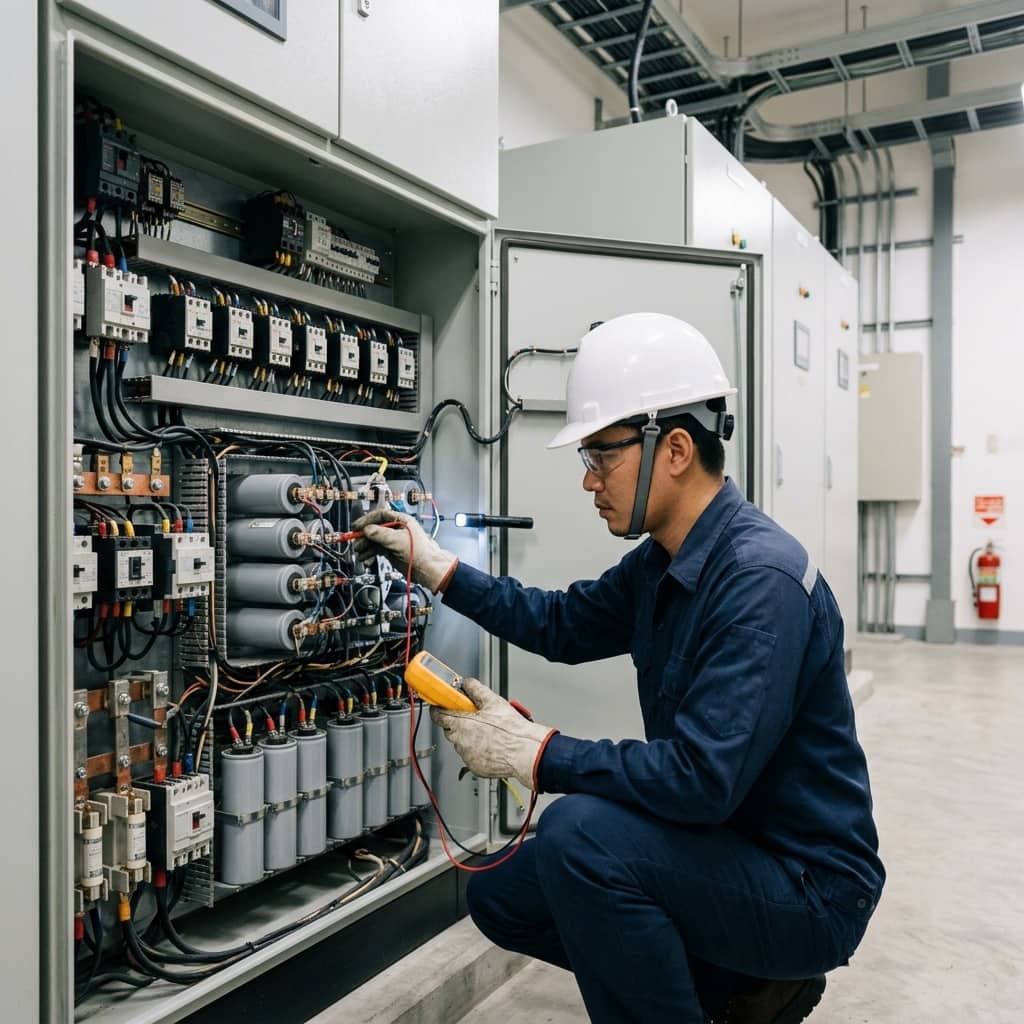
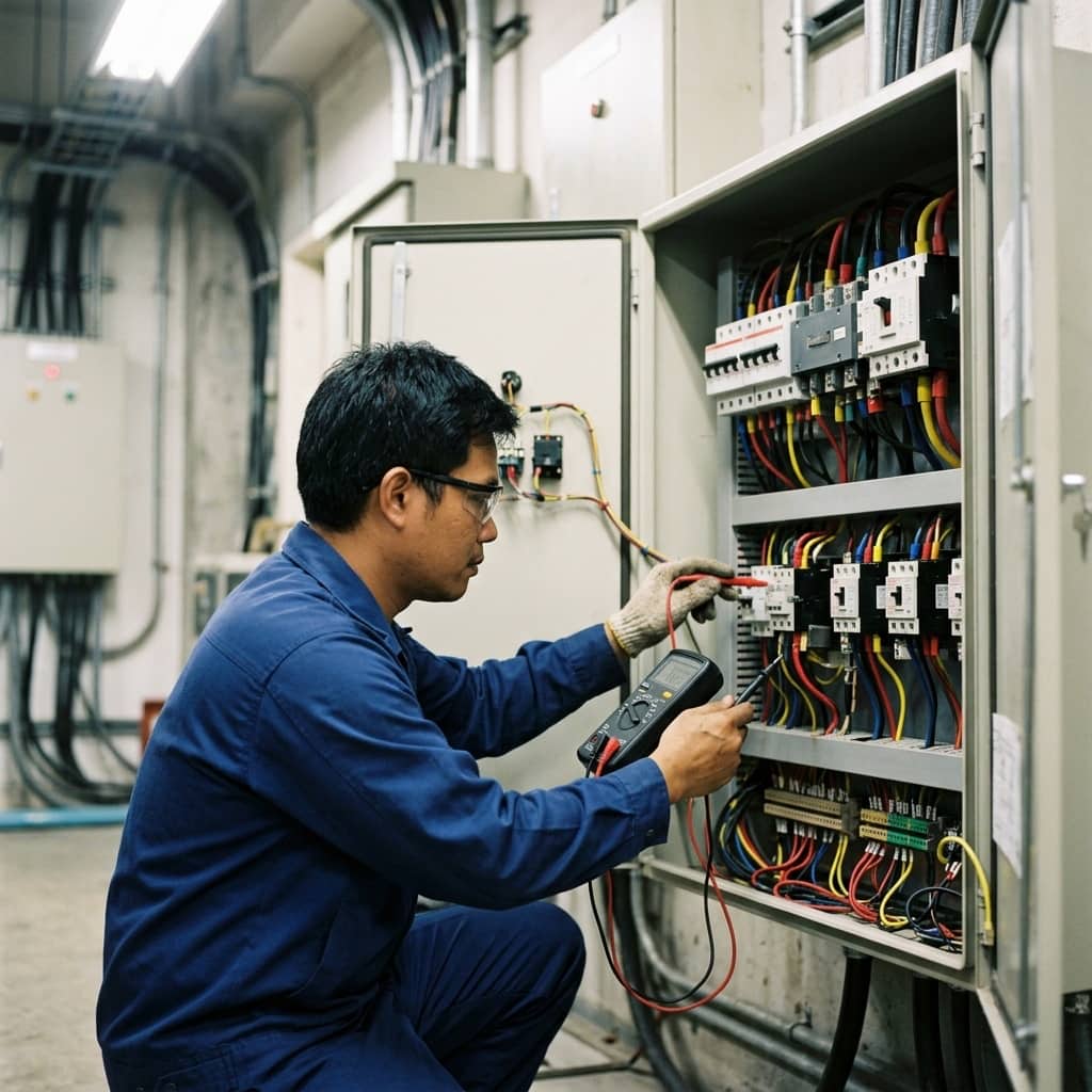
Testing begins without load: simulate a mains failure by opening the utility-side breaker or using the controller's test function, then time each stage — outage confirmation delay, generator start to voltage/frequency within limits, transfer to the standby source, and on utility restoration, the return confirmation delay, retransfer time, and engine cool-down before shutdown. All values are recorded against settings and design requirements.
An on-load test follows, confirming the generator accepts the step load without voltage or frequency dipping beyond limits. The interlock is proven by attempting to close both sources simultaneously in manual mode — the system must refuse in every case. Finally, abnormal scenarios such as a failed engine start should be simulated to verify the fail-to-start alarm, and the starting batteries and battery charger must always be tested as part of the same programme.
- Time the outage confirmation delay and generator start-to-ready interval
- Perform an on-load transfer and measure voltage and frequency under step load
- Prove both mechanical and electrical interlocks block source paralleling in all cases
- Simulate a fail-to-start event to verify alarm behaviour
- Check starting batteries and the battery charger every time
4. Common Failures and Preventive Maintenance
The leading cause of standby system failure at the moment of truth is silently degraded starting batteries — the charger still shows normal voltage while real capacity is gone. Next come degraded fuel or sediment-clogged filters, oxidised ATS contacts from long periods without operation, and undocumented changes to timer settings that leave the sequence inconsistent with the design.
Accepted preventive practice is periodic generator runs with actual load transfer, not just no-load running, since prolonged unloaded operation causes wet stacking in diesel engines. This is combined with battery capacity testing, fuel quality checks in the storage tank, re-torquing and thermal imaging of ATS connections, and keeping all controller settings in a change-controlled central register.
- Run periodic tests with real load transfer, not no-load running alone
- Capacity-test starting batteries rather than trusting float voltage
- Check stored fuel quality regularly
- Keep all controller settings in a change-controlled register
Need engineering consultation regarding Low Voltage & MDB?
The WIN TECH SERVICE engineering team is ready to provide site surveys, electrical system inspections, and prepare accurate legal certification reports.