MDB Panel Design: Understanding Form 4b Internal Segregation
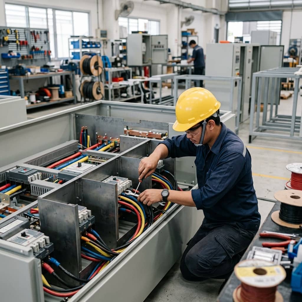
📌 Executive Summary
Preventing arc fault propagation by isolating busbars, functional units, and external terminals with metallic barriers.
1. Why Internal Segregation in MDB Panels Matters
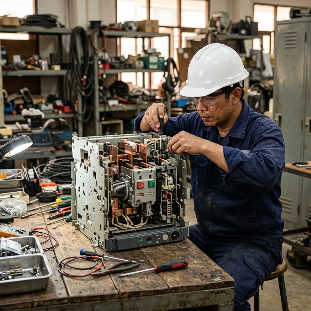
The Main Distribution Board (MDB) concentrates the entire electrical energy of a building or factory in one enclosure. If an internal arc fault occurs, the thermal energy released can destroy every neighbouring device and seriously injure personnel standing in front of the panel. Internal separation is therefore specified to confine damage to the compartment where the fault originates, preventing it from propagating to the main busbars or other functional units.
Equally important is safety during live maintenance. When a technician opens the door of one breaker compartment to inspect or replace a device, metallic barriers prevent hands or tools from accidentally reaching the energised main busbars. This allows a single outgoing circuit to be isolated while all other circuits continue to supply power, significantly reducing production downtime.
2. Form Separation Classes under IEC 61439-2
IEC 61439-2, the international standard for low-voltage switchgear and controlgear assemblies, defines internal separation classes from Form 1 (no separation) up to Form 4. Form 2 separates the busbars from the functional units; Form 3 additionally separates each functional unit from the others; and Form 4 fully separates busbars, functional units, and the external terminals of every circuit.
The difference between Form 4a and Form 4b lies in terminal location. In Form 4a the terminals share the compartment of their own functional unit, whereas in Form 4b each circuit's terminals occupy a dedicated compartment of their own. A technician can therefore access one circuit's terminals without ever exposing the breaker or terminals of any other circuit. MDBs for high-availability facilities such as hospitals, data centres, and continuous-process plants commonly specify Form 4b in their procurement documents.
- Form 1: no internal separation, suitable for small assemblies
- Form 2a/2b: busbars separated from functional units
- Form 3a/3b: functional units additionally separated from each other
- Form 4a: terminals located in the same compartment as their functional unit
- Form 4b: each circuit's terminals in an independent compartment — the highest safety level
3. Design and Acceptance Practices for Form 4b Assemblies
At the design stage, the panel builder must use barrier plates that have been design-verified together with the enclosure system per IEC 61439-1, not site-fabricated sheet steel. Particular care is needed at busbar tap-off and control-wiring penetrations, where grommets or gland plates must maintain at least IP2X internally so that the standard test finger cannot reach live parts.
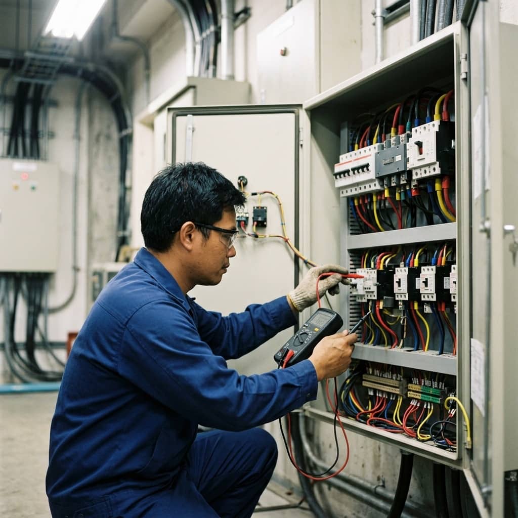
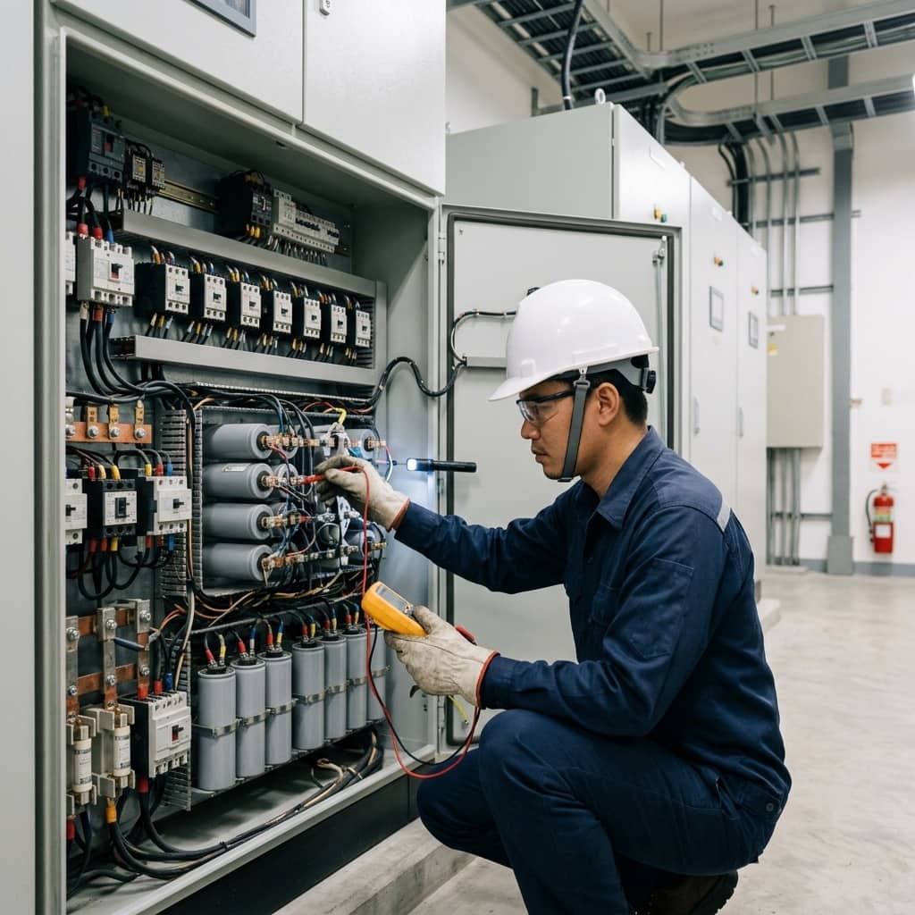
During site acceptance, the engineer should request the assembly's design verification report, confirm every barrier shown on the shop drawings is installed, and open the terminal compartments to verify that live parts of adjacent circuits are neither visible nor accessible. Air clearance and creepage distances at barrier penetrations should also be checked, as these are commonly compromised when panels are modified after delivery.
4. Common Problems and How to Prevent Them
The most frequent problem is post-installation modification: new circuits are added and the barriers are never fully reinstated, or a barrier removed temporarily during repair is simply forgotten. The assembly silently degrades from the Form 4b it was purchased as. Another case is routing additional control wiring through barriers without bushings, which both lowers the internal IP rating and creates a path for arc propagation between compartments.
Effective prevention relies on a management-of-change procedure for every panel modification, with approval from the original panel builder or the responsible engineer before work begins. Keep a barrier inventory in the as-built drawings, and include barrier completeness checks in the annual preventive maintenance checklist, together with thermal imaging of busbar joints through infrared windows where fitted.
- Control every panel modification through a management-of-change procedure
- Keep a barrier inventory in the as-built drawings for traceability
- Verify barrier completeness in the annual PM checklist
- Use bushings at every wiring penetration through a barrier
Need engineering consultation regarding Low Voltage & MDB?
The WIN TECH SERVICE engineering team is ready to provide site surveys, electrical system inspections, and prepare accurate legal certification reports.