Automatic Power Factor Correction (APFC) & Capacitor Bank Maintenance
📌 Executive Summary
Replacing swollen capacitors, checking discharge resistors, inspecting detuned reactors, and optimizing reactive power PF >= 0.95.
1. Why Power Factor Correction Matters
Most industrial loads — motors, transformers, ballasts — are inductive and draw reactive power (kvar), depressing the power factor. The consequences are unnecessarily high current in cables and transformers, resistive heat losses, voltage drop at the far end, and reduced real-power (kW) capacity of the transformer. Installing a capacitor bank to supply reactive compensation at the point of use lowers the total current and restores system capacity.
Commercially, medium and large utility customers in Thailand incur a power factor charge when reactive demand exceeds the tariff's allowed proportion of real demand. Keeping PF at roughly 0.95 or better therefore avoids the monthly penalty while simultaneously cutting internal losses. An Automatic Power Factor Correction (APFC) panel that switches capacitor steps in and out to follow the actual load is standard equipment in a modern factory MDB.
2. APFC Components and the Impact of Harmonics
An APFC panel comprises a PF controller fed from a main-side CT, capacitors arranged in multiple step sizes, capacitor-duty contactors with pre-charge resistors to damp inrush, per-step fuse or breaker protection, and discharge resistors that must bring the residual capacitor voltage down to a safe level within the time required by the product standard after disconnection — protecting technicians and preventing re-energisation onto trapped charge.
In plants with substantial power-electronic loads such as VFDs, welders, and UPS units, harmonic currents flow readily into the capacitors because capacitor impedance falls with frequency, and parallel resonance with the transformer inductance can amplify them, overheating and swelling the capacitors and shortening their life. The standard remedy is a detuned reactor in series with each capacitor step, shifting the resonance point away from the dominant harmonic orders in the system.
- A PF controller with a main-side CT measuring the true load
- Capacitor-duty contactors with inrush-damping resistors
- Discharge resistors to bleed residual voltage after disconnection
- Detuned reactors for systems with significant harmonics
- Individual fuse or breaker protection per step
3. Maintenance Procedure and Capacitance Measurement
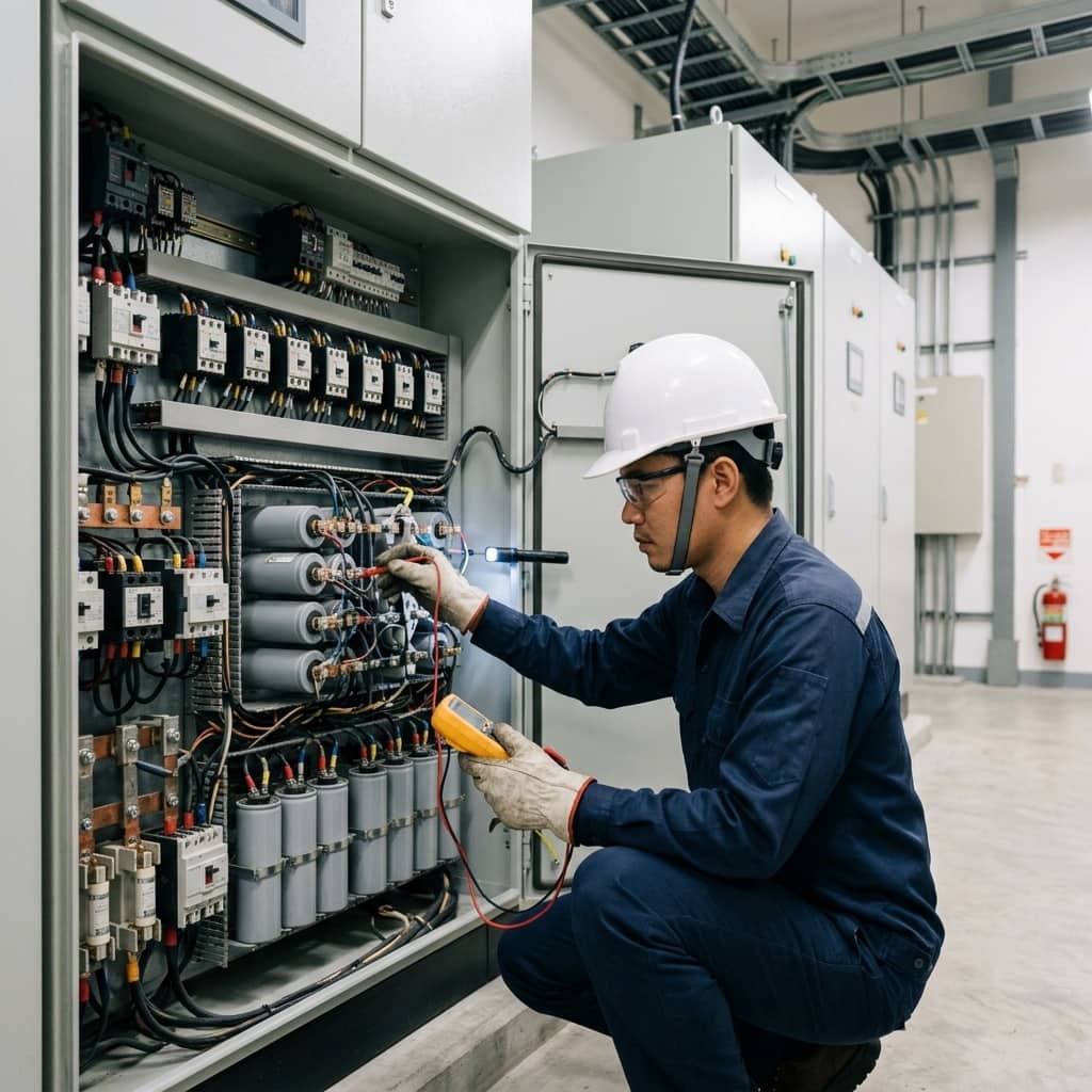
Capacitor panel maintenance begins with isolation, waiting out the discharge time stated on the equipment label, then verifying zero residual voltage and applying earths before touching anything. Each capacitor is inspected externally, with special attention to case swelling — a sign of internal dielectric degradation and an overpressure disconnector close to operating. The capacitance of each unit or phase is measured in microfarads against the nameplate; a drop beyond the manufacturer's tolerance indicates partial internal film failure and reduced delivered kvar.
In parallel, the contactor contacts — the panel's main wear item — are inspected; thermal imaging under real load reveals loose joints and abnormally hot reactors; the controller is exercised to confirm correct step sequencing; and ventilation fans and filters are checked, since elevated ambient temperature directly accelerates capacitor ageing. The job concludes by reading the actual PF at the utility meter against the target to confirm overall system performance.
4. Common Degradation Modes and Life-Extension Practices
The most common finding is swollen capacitors with reduced capacitance from accumulated heat and harmonics. Next are contactor contacts welded by repeated inrush when one step cycles abnormally often due to unsuitable C/k settings or step sizing. Open discharge resistors — invisible externally yet leaving dangerous trapped voltage — and single-phase blown fuses causing unbalanced operation while the controller still reads normal are also frequently found.
Proven life-extension measures include keeping the panel's internal temperature within the manufacturer's range through adequate ventilation, selecting capacitors rated above system voltage when used with detuned reactors (the reactor raises the voltage across the capacitor), rotating the step-switching order to equalise wear, measuring capacitance and checking all fuse phases annually, and re-sizing the compensation bank whenever major loads are added or removed.
- Keep panel temperature within the manufacturer's range
- Use higher-voltage-rated capacitors when detuned reactors are fitted
- Measure capacitance and check every fuse phase annually
- Re-size the bank when plant loads change significantly
Need engineering consultation regarding Low Voltage & MDB?
The WIN TECH SERVICE engineering team is ready to provide site surveys, electrical system inspections, and prepare accurate legal certification reports.