Zero Export Controller & Smart Power Sensor Installation for Self-Consumption Solar

📌 Executive Summary
Fast RS-485 loop control matching solar generation dynamically to real-time plant power consumption without feeding back to grid.
1. How Zero Export Controllers Work and When They Are Required
Many rooftop solar projects in Thailand are built to reduce a facility's own electricity cost without a power sales agreement. In these cases the utility requires measures preventing power from flowing back into the grid. A zero export controller meets this by measuring power at the connection point with a meter or smart energy sensor and continuously commanding the inverters to curtail output, keeping grid import above zero or above a configured minimum at all times.
The scheme is a closed control loop between the power sensor, controller, and inverters, communicating over protocols such as Modbus RTU/TCP. The critical variable is total loop speed — sensor sampling interval, controller processing time, and inverter response time — because when plant load drops suddenly, such as a large machine tripping offline, the system must curtail before reverse flow exceeds the duration the utility tolerates.
2. Utility Requirements for Non-Export Projects
A non-export interconnection application to PEA or MEA must show the reverse-flow prevention method in the submitted electrical drawings — either a reverse power relay that trips the circuit, or a zero export controller that curtails generation continuously. Each utility has detailed conditions such as accepted device models, sensor placement, and behavior to demonstrate at the acceptance test, which should be confirmed with the local district office before selecting equipment.
The behavior engineers must design explicitly is failure mode (fail-safe): if communication between sensor and inverters is lost, the system must fall to a safe state by automatically reducing output to zero or a minimum — not freeze at its previous level. This behavior is commonly tested at acceptance by physically disconnecting the communication cable in front of utility staff to confirm the inverters respond as designed within the required time.
- Show the reverse-flow prevention method in interconnection drawings
- Confirm device conditions with the local utility office
- Design fail-safe behavior for communication loss
- Prepare a live demonstration for the acceptance visit
3. Correct Installation and Configuration Steps
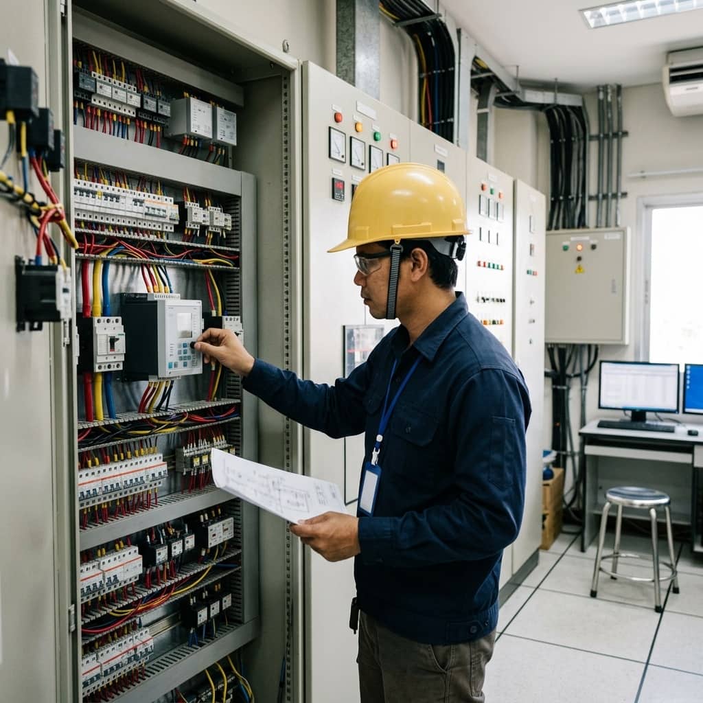
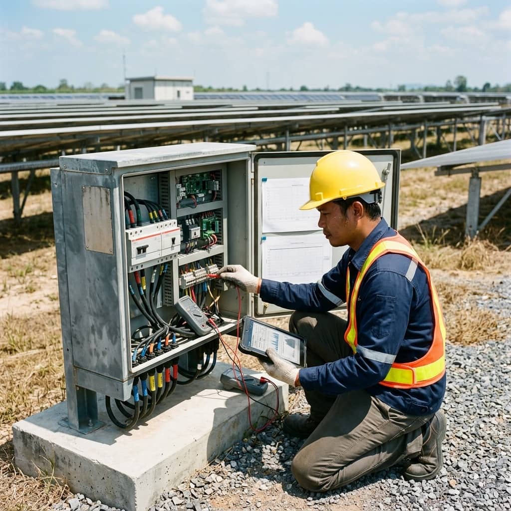
The power sensor must be installed where it sees the entire energy exchange with the grid — normally on the main incomer just downstream of the utility meter — and must cover all three phases, since some schemes control on the three-phase sum while some requirements evaluate per phase. Sensor CTs must match the main board's current rating and be mounted with the direction arrow per the manual. Communication cabling then runs to the controller and every inverter, avoiding routes parallel to power cables to limit interference.
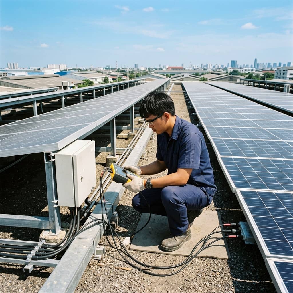
Configuration starts by setting the minimum import threshold agreed with the utility and the inverters' active power ramp parameters, then testing the full scenario set: sudden load loss, communication disconnection, and full power-cycle restart, recording the connection-point power graph during each test as evidence. Logging controller and inverter firmware versions in the handover documents also makes later troubleshooting far faster.
4. Common Field Problems and Fixes
Frequent problems include CTs mounted backwards or phase-mismatched with voltage references so the controller misreads power and curtails constantly; intermittent Modbus dropouts from unshielded cable or missing bus termination; response too slow to prevent brief reverse flow when load collapses; and inverters added later but never enrolled in the control loop, generating at full power uncontrolled.
Systematic fixes are to verify CT direction and phase pairing against a reference meter at commissioning; use shielded communication cable terminated per the bus standard; set the power ramp fast in the downward direction and slower upward to prevent oscillation; and make it a standing procedure that any inverter addition or replacement triggers a full re-test of the zero export loop.
- Cross-check the sensor against a reference meter after installation
- Use shielded communication cable with proper termination
- Ramp down fast, up slow, to prevent oscillation
- Re-test the loop after every inverter addition or replacement
Need engineering consultation regarding Solar & Clean Energy?
The WIN TECH SERVICE engineering team is ready to provide site surveys, electrical system inspections, and prepare accurate legal certification reports.