Grid Code Compliance for Commercial & Industrial Solar Inverters (PEA/MEA)
📌 Executive Summary
Overvoltage protection, LVRT (Low Voltage Ride Through), frequency control, and anti-islanding parameters for grid-tied solar systems.
1. What the Grid Code Is and Why Inverter Settings Matter
The grid code — the grid connection regulation — is the set of technical requirements that the Provincial Electricity Authority (PEA) and Metropolitan Electricity Authority (MEA) use to control the quality and safety of generation sources operating in parallel with the distribution network. The solar inverter defines the electrical behavior of the entire system, from the voltage and frequency windows within which it may feed power, to its response when the grid becomes abnormal. Incorrect settings can fail utility acceptance, or worse, endanger utility line crews.
Inverters connected in Thailand must be models tested and registered on the PEA/MEA approved inverter lists, which reference international standards such as IEC 62116 for anti-islanding protection. Using a listed model is not sufficient by itself, however: the installing engineer must also select the correct country grid profile and adjust parameters to match the requirements of the specific utility territory.
2. Key Parameters Specified by the PEA and MEA Grid Codes
The first parameter group is the operating voltage and frequency windows: the inverter must disconnect within a specified time when grid voltage or frequency leaves the acceptable range, and must apply a reconnection delay after the grid returns to normal. The second group is power quality — harmonic current limits, DC injection limits, and a power factor that must be controllable within the range the utility specifies.
The third group, increasingly prominent in modern requirements, is grid-support functions such as automatic power curtailment on over-frequency (frequency-watt or P(f) droop) and voltage-dependent reactive power control (volt-VAR), which keep distribution feeders with high PV penetration stable. Engineers should always consult each utility's latest published requirements before commissioning, as the codes are revised periodically as renewable penetration grows.
- Operating voltage/frequency windows and trip times
- Reconnection delay after grid recovery
- Harmonic limits, DC injection limits, and power factor range
- P(f) droop and volt-VAR functions per the latest utility notice
- Anti-islanding per the IEC 62116 test approach
3. Configuration and Testing Workflow for Interconnection Approval
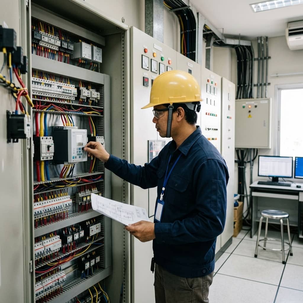
In practice, configuration starts by selecting the Thailand or utility-specific grid profile in the inverter firmware, then verifying each parameter against the requirement tables from the interconnection application. Do not trust profile defaults alone — different firmware versions can ship different presets. Capture screenshots or exported parameter files as evidence for the acceptance dossier.
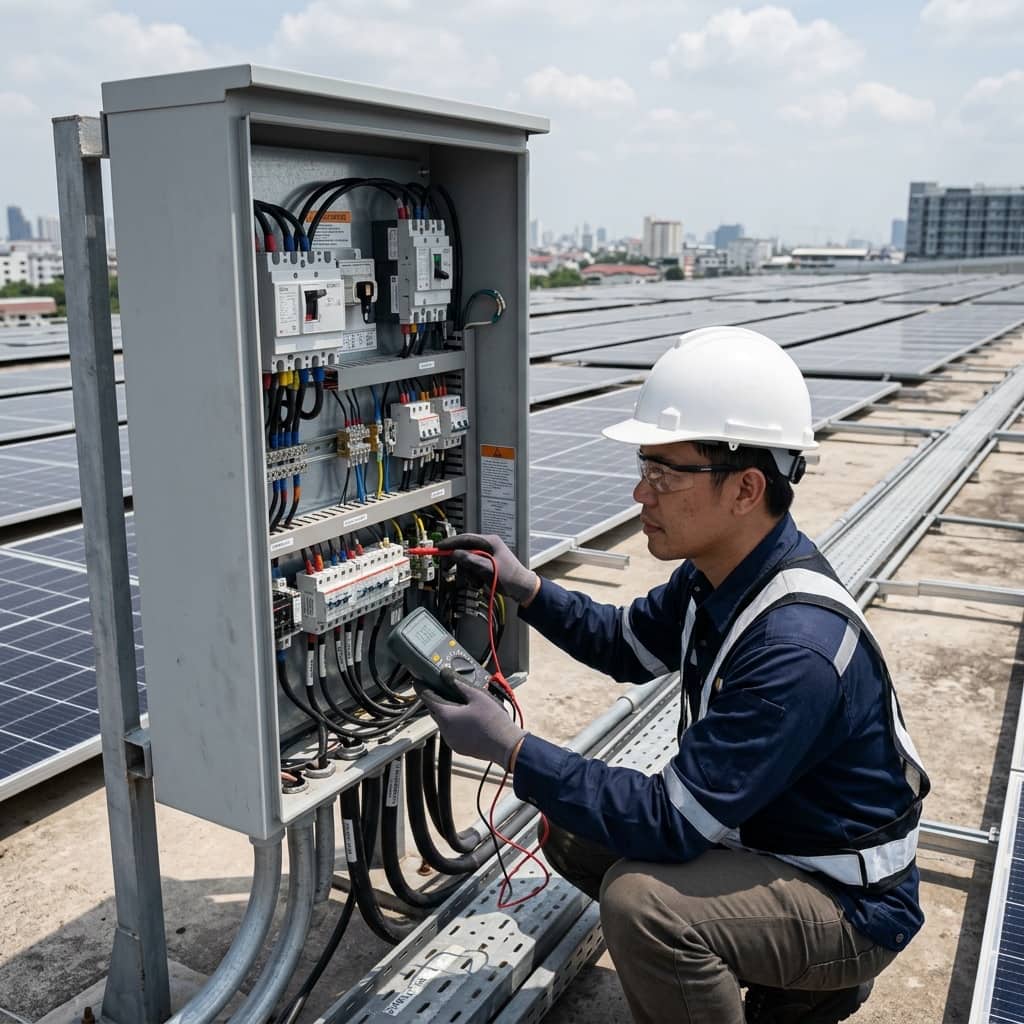
During the witnessed acceptance test with the utility, real functional tests are performed: disconnection on simulated loss of mains, measurement of cease-to-energize time, and cross-checking the inverter model against the approved register. The supervising engineer should prepare the single line diagram, protection test results, and a complete commissioning report before the appointment so that parallel operation is approved on the first visit.
4. Mistakes That Fail Acceptance and How to Avoid Them
Common causes of failed acceptance include selecting the wrong country grid profile so voltage/frequency windows don't match the code, running firmware different from the registered version, and incomplete documentation such as missing protection relay test results or drawings that don't match the site. Another problem group appears after energization: frequent tripping from high feeder-end voltage, common on long feeders with dense PV installations.
Avoid these by maintaining a per-project checklist of parameters against the latest code revision, pinning firmware to the registered version, and surveying actual voltage at the connection point under both high and low load before design. Where feeder voltage runs high, discuss volt-VAR activation or transformer tap adjustment with the utility — never widen the inverter's voltage window unilaterally, which violates the code and creates safety risk.
- Use a parameter checklist against the latest code for every project
- Pin inverter firmware to the registered version
- Survey connection-point voltage at high and low load before design
- Never widen voltage/frequency windows beyond the code unilaterally
Need engineering consultation regarding Solar & Clean Energy?
The WIN TECH SERVICE engineering team is ready to provide site surveys, electrical system inspections, and prepare accurate legal certification reports.