CT/PT Reverse Protection for Factory Solar Rooftops
📌 Executive Summary
Key safety interlocks required by PEA/MEA when connecting large-scale solar arrays to utility grids.
1. Why Factories with Solar Need Reverse Power Protection
When an industrial facility connects a solar rooftop system in parallel with the utility distribution network, there is a possibility that power from the inverters will flow back into the grid (reverse power flow) whenever the plant load drops below the PV output — for example during lunch breaks or on holidays when production lines are idle. This reverse flow affects the utility's existing protection equipment, can cause mal-operation of utility protection relays, and is explicitly regulated: both the Provincial Electricity Authority (PEA) and the Metropolitan Electricity Authority (MEA) require applicants for generator interconnection to provide clear control measures.
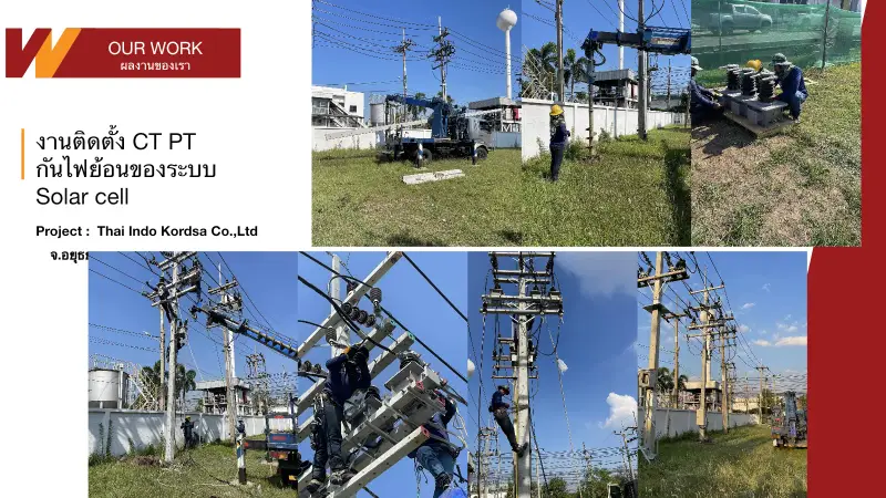
The core of the protection scheme is the current transformer (CT) and potential transformer (PT) installed at the point of common coupling (PCC), which measure the direction of power flow in real time and feed a directional/reverse power relay (ANSI 32). The relay trips the circuit or commands the inverters to curtail output when reverse flow exceeds the setpoint. Selecting the correct CT ratio, accuracy class, and burden is an engineering task that must be designed specifically for each plant.
2. Relevant PEA and MEA Interconnection Requirements
The grid connection codes of both PEA and MEA specify minimum protection equipment for grid-parallel generation, scaled by installed capacity and connection voltage level. For projects that do not export energy (non-export schemes), the utility requires reverse-flow protection such as a reverse power relay or a zero export controller, together with a single line diagram certified by a licensed professional electrical engineer as part of the interconnection application.
Beyond the directional power relay, the requirements cover complementary protection functions: over/under voltage (ANSI 59/27), over/under frequency (ANSI 81O/81U), and anti-islanding protection, which utility-registered inverters must support. CT/PT placement must therefore be engineered for the coordinated operation of all these functions, not designed piecemeal device by device.
- Reverse power relay (ANSI 32) at the point of common coupling
- Over/under voltage and frequency protection (ANSI 59/27, 81O/81U)
- Anti-islanding per registered inverter standards
- Single line diagram certified by a licensed electrical engineer
- Witnessed commissioning tests with the utility before parallel operation
3. Practical CT/PT Design and Installation Approach
Design work begins with analyzing the plant load profile against the PV output to determine CT locations that cover every path through which current could flow back to the grid, typically on the LV or HV side of the main transformer depending on the connection voltage. The CT ratio must be chosen so that the minimum reverse current to be detected falls within the relay's accurate measurement range, and the total burden of wiring plus relay must be verified against the CT rating.
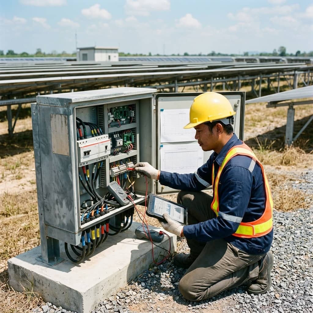
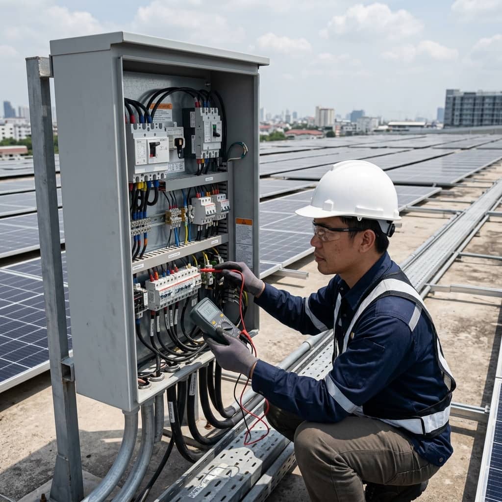
During installation, CT polarity must be observed strictly — a reversed connection makes the relay read power direction incorrectly and fail to trip on a real reverse-flow event. After installation, verify the scheme with secondary injection tests and a directional test under real load, and record all relay settings in the handover documentation for reference during annual inspections.
4. Common Problems and How to Prevent Them
The most frequent finding when auditing reverse-flow protection is CT polarity or phase-sequence errors, which show no symptoms in normal operation but cause the protection to fail during a real event. The next most common issue is over-sensitive relay settings that cause nuisance trips during load swings such as large motor starts, needlessly costing the plant its solar production.
Prevention comes from performing a directional test under real load after every installation or measurement-circuit modification, setting relay time delays consistent with the plant's actual load behavior within what the utility code permits, and re-verifying the scheme during annual substation maintenance — plus re-checking all settings whenever the PV system is expanded or major plant loads change.
- Verify CT polarity and phase sequence with a real-load test every time
- Tune relay time delays to actual load behavior to reduce nuisance trips
- Re-verify settings after PV expansion or major load changes
- Fold relay testing into the annual maintenance program
Need engineering consultation regarding Solar & Clean Energy?
The WIN TECH SERVICE engineering team is ready to provide site surveys, electrical system inspections, and prepare accurate legal certification reports.