Causes and Mitigation of Transformer Noise & Vibration
📌 Executive Summary
Understanding magnetostriction in silicon steel cores, resonance, harmonic distortion, and mechanical damping solutions.
1. Where Transformer Noise Comes From: Core Magnetostriction
The characteristic transformer hum originates primarily from magnetostriction — the minute elongation and contraction of the silicon steel core laminations as the magnetic field alternates. Because this dimensional change happens twice per electrical cycle, the fundamental tone of a transformer on a 50 Hz system is 100 Hz, with harmonics at 200, 300, and 400 Hz. Some noise is therefore inherent to every transformer, and guaranteed sound levels are specified against the IEC 60076-10 measurement standard.
Beyond the core, secondary sources include electromagnetic forces between windings vibrating with load current (also 100 Hz, but load-dependent in magnitude) and cooling equipment — fans and oil pumps — whose acoustic character is clearly different. Distinguishing the source is the first diagnostic step: core noise tracks voltage, winding noise tracks load, and fan noise follows the cooling stages. Observing which condition changes the sound localizes the cause without sophisticated instruments.
2. Causes of Abnormally Loud Operation
When a previously quiet transformer grows louder, the first suspect is system overvoltage or an unsuitable tap setting: core noise is highly sensitive to flux density, and a voltage rise of only a few percent pushes the core toward saturation with a clearly audible result. Next come harmonic currents from non-linear loads — variable frequency drives and chargers — which raise both noise and heating, and stray DC bias in the system, which half-cycle-saturates the core and produces a distinctive harsh growl.
Mechanical causes include core clamping bolts and structures loosening with age, letting laminations rattle against each other; external parts — radiators, covers, control cabinets, rain shields — coming loose and resonating at 100 Hz; and, most severe, resonance of the supporting structure or the room itself, which amplifies otherwise normal noise into a building-wide disturbance. Typical industrial plants mounting transformers on steel frames or in hard-walled rooms should address this at the design stage.
- Overvoltage or wrong tap: core nears saturation, noticeably louder
- Harmonics from non-linear loads (VFDs, chargers): more noise and heat
- DC bias: half-cycle core saturation with a harsh growl
- Loosened core clamping / loose external parts resonating at 100 Hz
- Resonance of the supporting structure or installation room
3. Systematic Measurement and Diagnosis
Diagnosis should start with electrical data before acoustic instruments: log system voltage against the present tap rating, examine the load current harmonic spectrum with a power quality analyzer, and compare noise levels at different loads. Noise that clearly tracks voltage points to the core and tap setting; noise that tracks load points to the windings and harmonics. This groundwork narrows the field before investing in detailed measurement.
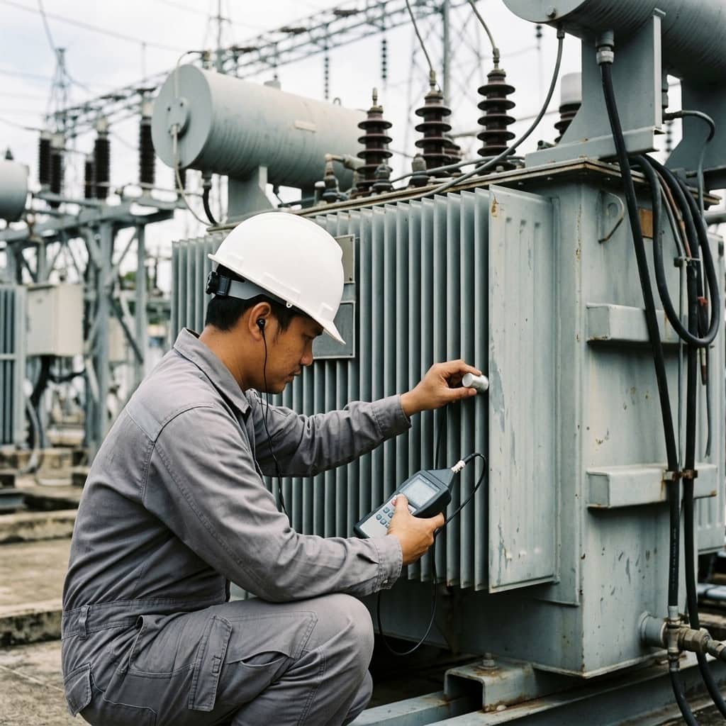
Detailed work uses sound level measurement per IEC 60076-10 for comparison with the factory guaranteed value, and vibration measurement with accelerometers at multiple tank wall positions followed by frequency spectrum analysis. Energy concentrated at 100 Hz and its even harmonics is the signature of magnetic sources, whereas odd peaks that are not harmonics of 100 Hz typically reveal mechanical resonance of a specific component. Walking the tank with a contact probe point by point, combined with thermal imaging, is an effective way to pinpoint loose elements.
4. Remedies That Actually Work
Fix causes before symptoms. If system voltage is high, correcting the tap position often reduces noise immediately at zero cost. If harmonics are high, consider harmonic filters or load regrouping. Loose external parts should be tightened with rubber isolation pads added; resonating elements can often be cured by adding mass or stiffeners to shift their natural frequency away from 100 Hz. Loosened internal core clamping is tank-opening work whose economics must be weighed against the unit's remaining life.
Where the transformer itself is healthy but neighbors are disturbed, acoustic remedies include anti-vibration mounts under the transformer base, flexible connections at busbars and piping to break vibration transmission paths into the building structure, and acoustic barrier walls facing sensitive areas. The key principle: structure-borne vibration is usually the dominant path rather than airborne sound, so breaking mechanical transmission paths achieves more than absorptive lining alone.
Need engineering consultation regarding Transformer?
The WIN TECH SERVICE engineering team is ready to provide site surveys, electrical system inspections, and prepare accurate legal certification reports.