Operation and Testing of Buchholz Relays in Transformer Protection
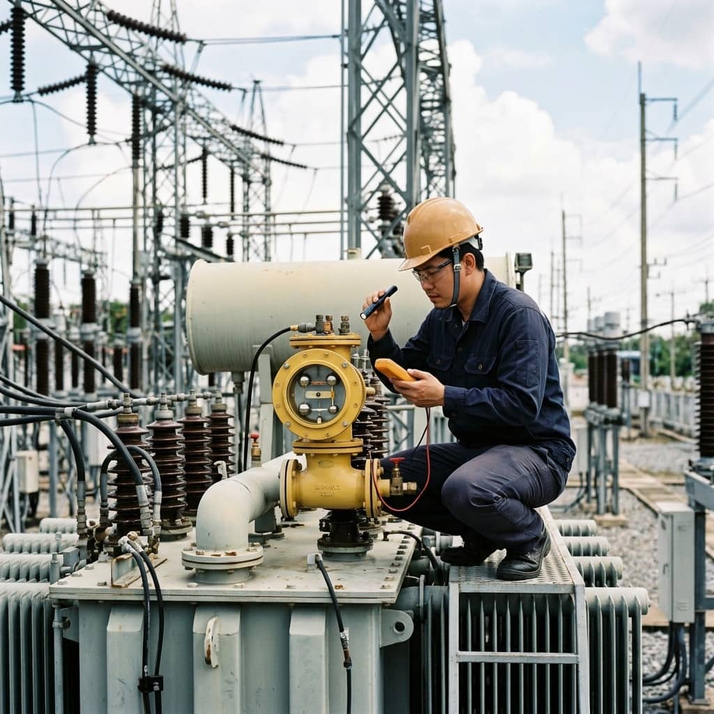
📌 Executive Summary
How Buchholz relays detect incipient internal faults, arc discharges, and gas accumulation in oil-immersed transformers.
1. How the Buchholz Relay Works
The Buchholz relay is a mechanical protection device mounted in the pipe between the main tank and the conservator of conservator-type oil transformers. It exploits a simple but powerful fact: almost every internal fault decomposes oil or insulation into gas. The gas rises through the pipe and accumulates in the relay body, sinking the upper float and closing the alarm contact — signaling trouble without immediately tripping the transformer.
For severe faults such as internal short circuits or high-energy arcing, oil is violently expelled toward the conservator at high velocity. This oil surge strikes the flap (baffle) of the lower float, closing the trip contact and opening the circuit breaker instantly to limit damage. This two-stage mechanism lets the Buchholz relay detect both slowly developing incipient faults and sudden catastrophic ones — coverage that external electrical relays alone cannot fully provide.
2. Correct Installation Practice
Buchholz relay effectiveness depends heavily on installation. The pipe between the main tank and conservator must rise toward the conservator at the manufacturer's specified inclination (typically around 3 to 7 degrees) so gas travels freely into the relay rather than pocketing in the pipe. The relay body must be mounted with its casing arrow pointing toward the conservator, following the oil flow direction, and positioned where the gas sight glass can be read and gas samples collected.
A frequently overlooked detail is venting after oil filling or maintenance. Trapped air rises into the relay and produces nuisance alarms during the first weeks of service, so the relay's bleed valve must be opened until oil flows continuously. The wiring from the relay contacts to the trip circuit must also be properly segregated and protected from interference, because this circuit trips the HV breaker directly — a wiring fault means either spurious trips or a failure to trip when it matters most.
3. Functional Testing on the Maintenance Cycle
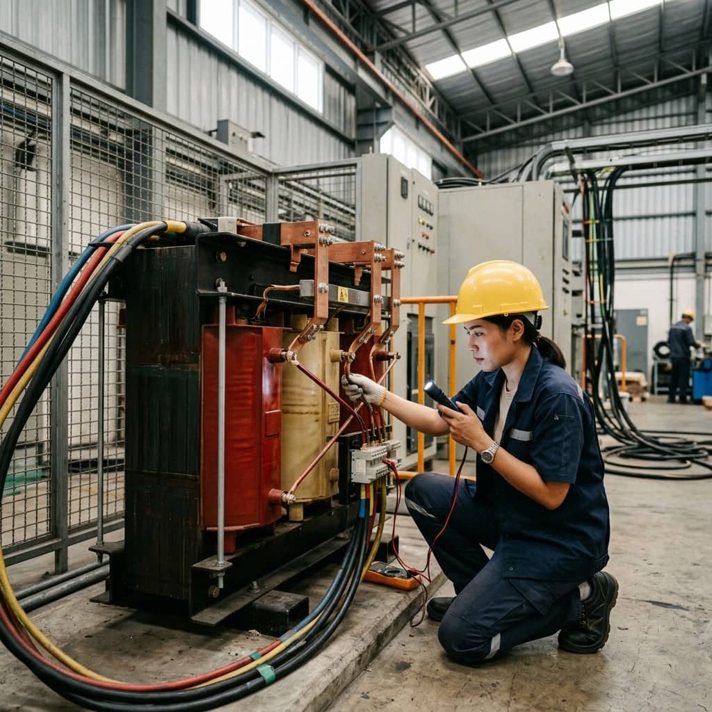
Buchholz relay testing belongs in every major maintenance outage. The most basic method is pressing the mechanical test push button on the relay (where fitted) to simulate operation of both float assemblies, then verifying that the alarm and trip signals actually reach the control panel and breaker. A more complete method injects dry air or nitrogen through the test valve to simulate genuine gas accumulation, confirming the upper float operates at the manufacturer's specified gas volume.
The full signal path must be proven end to end — relay contacts, wiring, auxiliary relays, and the breaker trip coil — because the usual point of failure is not the Buchholz device itself but the circuit in between, such as loose terminals or aged auxiliary relays. During the test, also inspect the sight glass, gaskets, and housing for leaks. When the transformer returns to service, record that the relay is functional and that no residual gas remains visible in the sight glass.
- Press the mechanical test button to simulate both float assemblies
- Inject dry air/nitrogen via the test valve to verify actual operating points
- Prove the complete signal path through to the breaker trip coil
- Inspect the sight glass, gaskets, and housing for leaks in the same visit
- Bleed air from the relay before every re-energization
4. Interpreting a Real Relay Operation
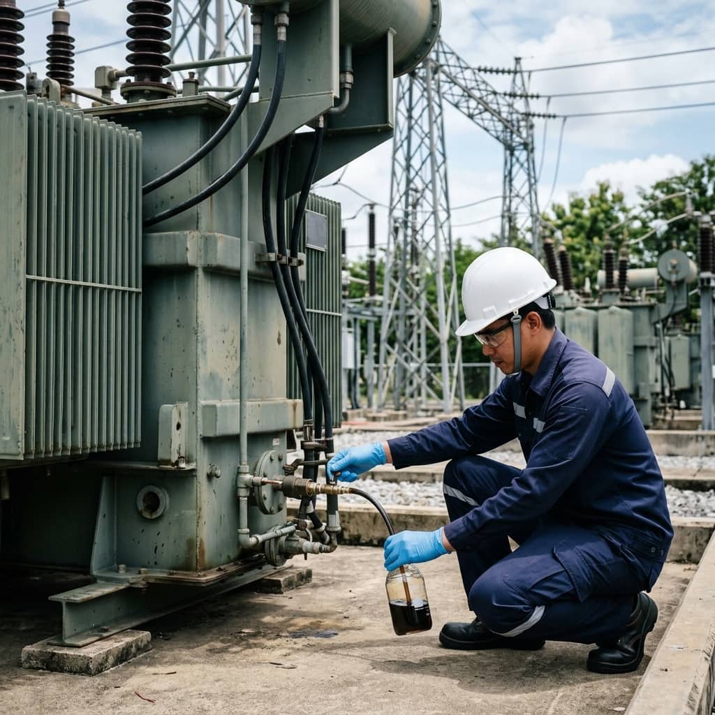
When a Buchholz alarm operates, the first action is to safely draw a gas sample from the relay for analysis before any other decision. Gas color and flammability give initial clues: colorless, non-flammable gas is usually trapped air, while grey or black flammable gas indicates oil or insulation decomposition from heat or arcing. Laboratory DGA of both the gas and the oil confirms the fault type most reliably.
If the relay has tripped, the transformer must never be re-energized until an internal fault has been ruled out — re-energizing into an internal short can escalate damage to tank rupture or fire. The correct procedure is a full diagnostic suite: insulation resistance, turns ratio, winding resistance, and DGA compared against baseline data. Known causes of spurious operation — trapped air after maintenance, low oil level, or severe external vibration — should be systematically eliminated before concluding that a genuine internal fault exists.
Need engineering consultation regarding Transformer?
The WIN TECH SERVICE engineering team is ready to provide site surveys, electrical system inspections, and prepare accurate legal certification reports.