Structural Roof Load Capacity & Wind Load Verification for Solar Panel Mounting

📌 Executive Summary
Ensuring Metal Sheet and Concrete Slab roofs satisfy dead load and wind uplift constraints according to building codes.
1. Why Structural Assessment Must Precede Rooftop Solar
Most factory roofs in Thailand are steel structures with metal sheet cladding, designed only for their own weight and the live loads of the original building code — not for the solar modules, rails, mounting hardware, and installation and maintenance loads that will be added for a system life of over twenty years. Installing without assessment risks cumulative purlin deflection, leaks at over-stressed fixing points, and in severe cases structural failure of the roof frame.
Assessment must consider both the added dead load of the PV system and wind load, which matters just as much: modules change airflow over the roof surface, producing localized uplift forces higher than on a bare roof, especially at building edges and corners. Structural assessment is joint work between a civil engineer evaluating the existing structure and the engineer designing the mounting system, and a licensed engineer must certify the result.
2. Assessment Criteria and Applicable Standards
Wind load calculation for buildings in Thailand references the Department of Public Works and Town & Country Planning wind load standard (DPT 1311), which defines reference wind speeds by area, terrain factors, and pressure coefficients by building geometry. Verification of the existing steel structure uses the applicable steel design standards combined with field survey data — actual member sizes, corrosion, and accumulated deflection of purlins and trusses.
Beyond calculation, a site survey must confirm the original construction drawings match reality: many industrial buildings have additions or suspended services beyond the original design — ducting, cable trays, overhead cranes — that have already consumed part of the structure's reserve capacity. The assessment concludes with the allowable additional load per square meter, zone-by-zone panel placement limits, and reinforcement requirements where needed.
- Wind loads calculated per the DPT 1311 standard
- Existing steel capacity checked against field survey data
- Survey of additions and services hung beyond original drawings
- Zone-by-zone allowable load with reinforcement requirements
- Assessment certified by a licensed engineer
3. Survey Workflow and Mounting System Design
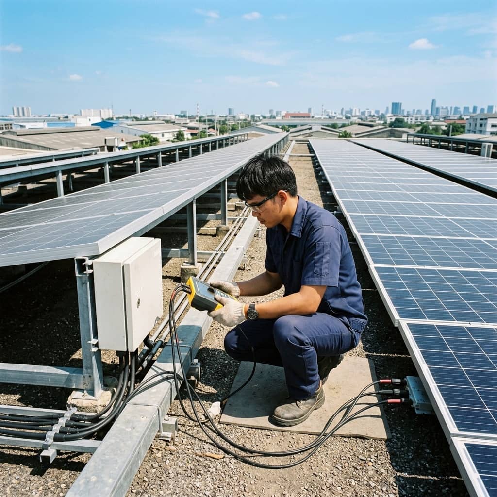
Field survey work measures actual sections of purlins, rafters, and trusses; checks purlin spacing against rail attachment points; documents existing damage such as rust, cracked welds, or deteriorated sheeting; and inspects the original roof sheet fasteners. This data feeds a structural model to analyze remaining capacity, from which the panel layout is planned to route weight into the positions the structure carries best.
Mounting on metal sheet roofs typically uses standing seam clamps or brackets screwed directly to purlins with waterproofing systems; the choice depends on sheet type and the uplift analysis. Critically, fixing pull-out strength must be verified by test or manufacturer certification, and fixing spacing at building edges must tighten according to zone-specific wind coefficients — never a single uniform spacing across the whole roof.
4. Common Risks and Mitigation Approaches
Frequent project risks include using catalogue module weight while forgetting rails, hardware, and cabling; placing edge-zone panels with the same fixing spacing as the roof center; missing the purlin when drilling so fixings bear on bare metal sheet; and installers walking the roof sheet during construction, denting it until it leaks. These problems rarely show immediately but accumulate into leaks and deflection after a period of service.
Mitigation comes from shop drawings that locate every fixing against actual purlin lines from the survey, defined walk paths and load-spreading boards during installation, construction-phase inspection by supervisors who understand both structure and waterproofing, and a check after the first major storm season to confirm fixings and waterproofing are performing as designed.
- Always include rails, hardware, and cabling in load calculations
- Tighter fixing spacing in edge zones than mid-roof
- Shop drawings referenced to surveyed purlin lines
- Inspect fixings and waterproofing after the first storm season
Need engineering consultation regarding Solar & Clean Energy?
The WIN TECH SERVICE engineering team is ready to provide site surveys, electrical system inspections, and prepare accurate legal certification reports.