Motor Control Center (MCC) Starter Types: DOL, Star-Delta, Soft Starter, VFD

📌 Executive Summary
Comparing starting current surges, torque characteristics, and mechanical stress on motor shafts across starter topologies.
1. The MCC and Why Multiple Starting Methods Exist
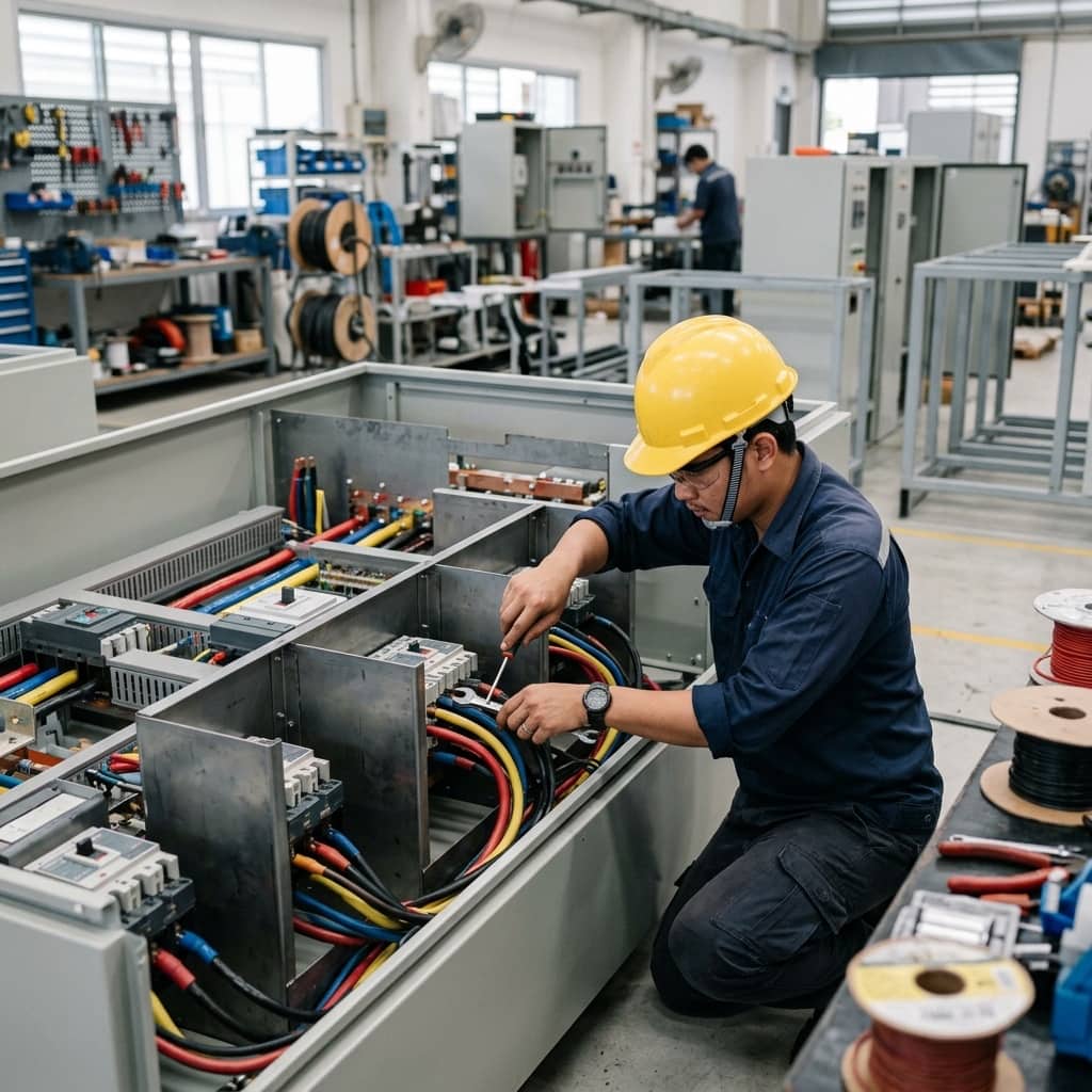
A Motor Control Center (MCC) gathers many motor starters into one structure, each bucket containing a disconnect, overload protection, a contactor or starting device, and control circuitry. Multiple starting methods exist because a squirrel-cage induction motor started direct-on-line draws roughly six to eight times its rated current. This inrush depresses system voltage, disturbs other equipment, and the accompanying torque shock stresses shafts, couplings, and the driven load.
Choosing a starting method therefore balances electrical system limits (permissible voltage dip, transformer size), the mechanical load's needs (breakaway torque, pump, fan, or conveyor characteristics), and budget — from the simplest Direct On Line to the fully controllable Variable Frequency Drive. The MCC designer must understand each method's characteristics to assign the right starter type to every motor in the plant.
2. Comparing DOL, Star-Delta, Soft Starter, and VFD
Direct On Line gives full starting torque with the simplest circuit, suiting small motors on systems that tolerate the inrush. Star-delta starting reduces winding voltage by one over root three, cutting both current and torque to about one-third of DOL values — workable for light-starting loads such as fans and centrifugal pumps, but weakened by a second current surge at the star-to-delta transition and the need for six-lead motors.
A soft starter uses thyristors to ramp voltage smoothly over a set time, controlling starting current continuously without transition shocks, and usually offers a soft-stop function that reduces water hammer in pump systems. A VFD independently synthesises frequency and voltage, starting at near-rated current, providing continuous speed control in operation, and delivering large energy savings on variable-torque loads like fans and pumps — at the highest cost, with heat dissipation in the panel and added harmonic and high-frequency leakage issues to manage.
- DOL: simplest and cheapest, full torque, but 6–8x inrush
- Star-Delta: current and torque cut to ~1/3, with a transition surge
- Soft Starter: smooth voltage ramp, no transition shock, soft stop available
- VFD: lowest starting current, speed control, big savings on variable-torque loads
- Every method must be matched to the real load's torque profile
3. Motor Protection and Starter Component Coordination
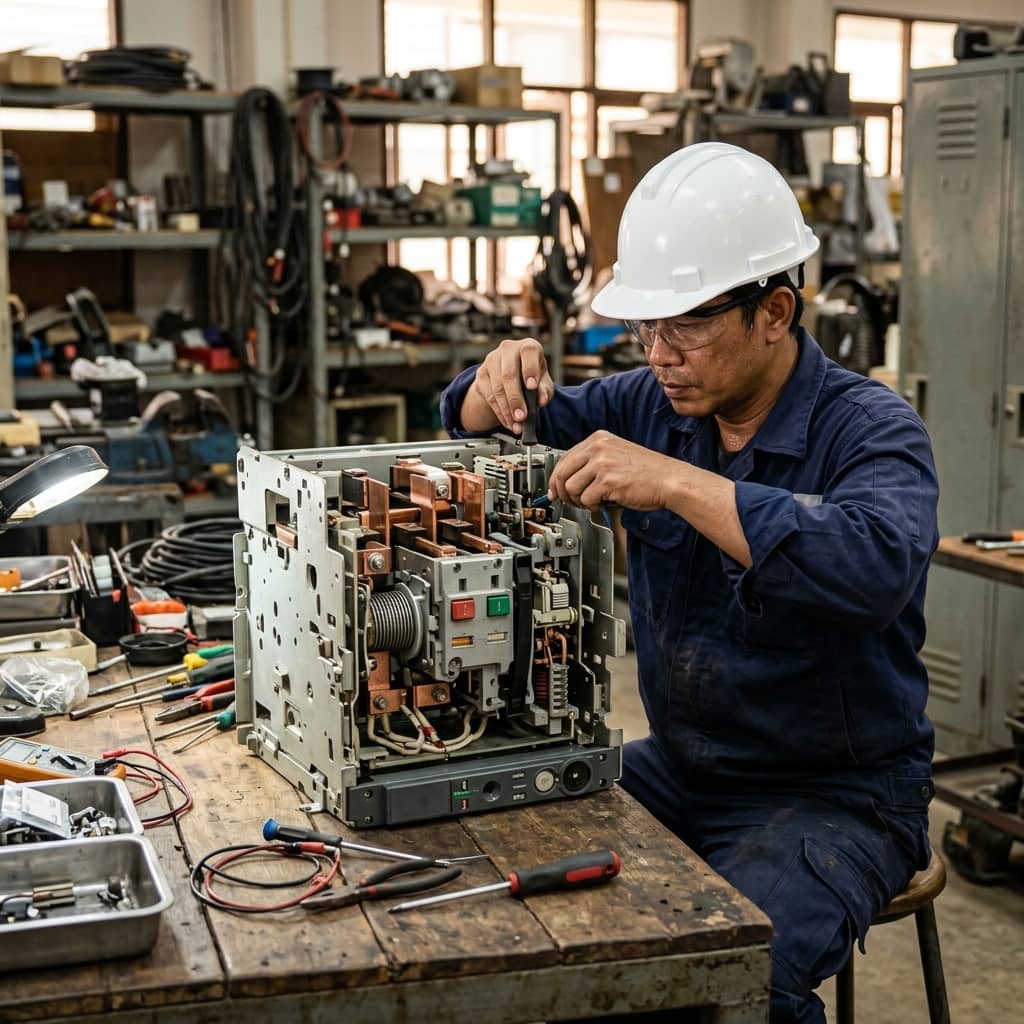
Every starter needs two protection layers: short-circuit protection by breaker or fuses, and overload protection by a thermal or electronic overload relay set to the motor nameplate current with a trip class matching the load's acceleration time — slow-accelerating loads such as large fans need longer classes to avoid tripping during the start. IEC 60947-4-1 further defines coordination types: Type 2 requires that after a short circuit the contactor and overload remain serviceable within defined damage limits.
Achieving Type 2 requires breaker–contactor–overload combinations from the manufacturer's jointly tested coordination tables, not piecewise selection by current rating. VFD starters add further considerations: shielded motor cable with correctly bonded shields, output filters on long runs to limit reflected-wave voltage that destroys winding insulation, and confirmation that any residual-current protection on the circuit is of a type compatible with the drive's leakage characteristics.
4. Common Field Problems in MCC Installations
Frequent findings include overload settings raised above the nameplate to silence nuisance trips without diagnosing the real cause — effectively removing motor protection; star-delta transition timers set poorly, causing re-arcing and welded contacts; clogged VFD compartment filters tripping drives on overtemperature in hot season; and control wiring pulled in the same tray as power cables, with induced noise corrupting the control system.
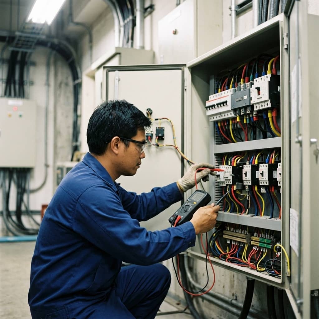
Prevention rests on a maintenance schedule covering joint re-torquing, thermal imaging with motors under real load, ventilation filter cleaning, functional testing of overload relays, and tracking contactor operation counts against the manufacturer's declared mechanical life. Every setting change must be logged with its justification, and whenever a motor or load is resized, the entire protection chain and starting method must be re-reviewed — not just the overload dial adjusted at the panel.
- Set overloads to the motor nameplate — never raise them to mask trips
- Clean VFD compartment ventilation filters on schedule
- Always separate control wiring trays from power cabling
- Track contactor operation counts against declared mechanical life
Need engineering consultation regarding Low Voltage & MDB?
The WIN TECH SERVICE engineering team is ready to provide site surveys, electrical system inspections, and prepare accurate legal certification reports.