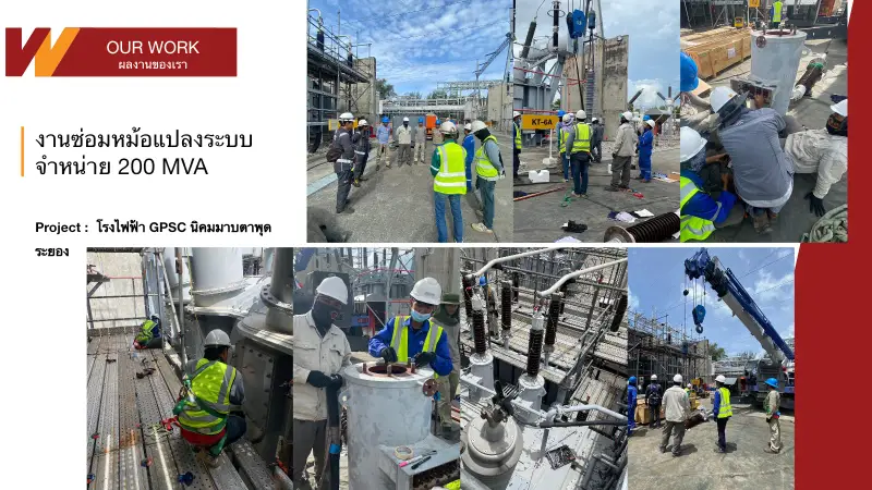
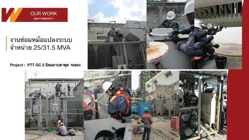
Overhaul Case Study: 200 MVA Substation Power Transformer
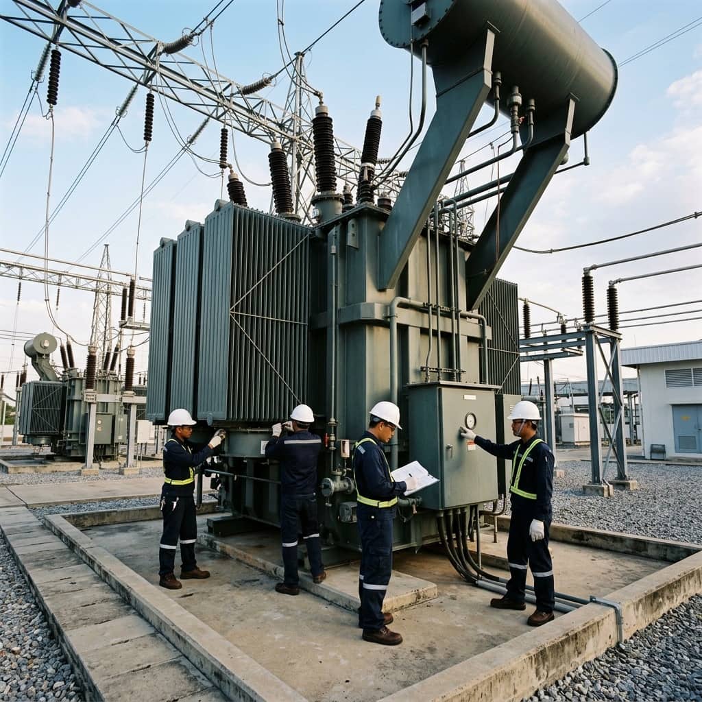
📌 Executive Summary
Engineering procedure for vacuum filling, core inspection, gasket renewal, and site acceptance testing (SAT) on 200 MVA units.
1. Overview of a Substation-Class Transformer Overhaul
A 200 MVA class power transformer is the backbone of a high-voltage substation, and a major overhaul of such a unit differs completely from routine distribution transformer work: tens of thousands of liters of oil to drain and manage, total weights of hundreds of tonnes, forced cooling systems (ONAF or OFAF) with numerous pumps and fans, and real transmission-grid consequences if the outage overruns. Planning must be detailed to the hour, covering engineering, rigging, safety, and contingency plans for damage worse than expected.
A typical overhaul scope includes internal tank and core inspection, renewal of every gasket and seal, repair or replacement of accessories — bushings, tap changer, cooling system — insulation system dry-out, vacuum oil filling, and a complete Site Acceptance Test (SAT) before energization. These stages chain together: an early mistake, such as leaving the insulation exposed to humid air too long, compounds into very expensive problems at the later stages.
2. Tank Opening, Internal Inspection, and Moisture Control
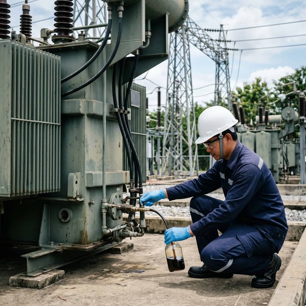
Before opening, the oil is drained to clean prepared storage with baseline samples sent for analysis. While the tank is empty of oil, the paper insulation absorbs atmospheric moisture rapidly — mandatory countermeasures are a continuous feed of low-dewpoint dry air into the tank for the entire open period and a strict limit on total tank-open hours in the work plan. Personnel entering the tank follow confined space procedures, wear clean lint-free clothing, and log every tool in and out so nothing is left behind inside.
Internal inspection concentrates on areas the test history has flagged: overheating traces or carbon at connections, winding clamping pressure that may have relaxed under accumulated short-circuit forces, the condition of paper insulation and pressboard barriers, displacement of internal lead supports, and the integrity of the core ground connection — which must exist at exactly one point. Multiple core grounds or leaking core insulation are the classic origin of circulating currents and the abnormal heating seen in earlier DGA. Every finding is photographed and documented to support the final repair scope decision.
- Continuous dry air feed and strict limits on tank-open hours
- Confined space procedures with full tool in/out logging
- Inspect winding clamping pressure, connections, and insulation barriers
- The core ground must be a single point — multiple grounds cause circulating currents
- Photograph and document all findings to set the final repair scope
3. Dry-Out, Vacuum Oil Filling, and Reassembly
With internal repairs complete and all gaskets renewed, the most critical phase is dry-out and vacuum filling. The tank is sealed and pulled to deep vacuum to extract moisture from the insulation and evacuate air from every winding crevice. Dryness is judged by a pressure rise test: with the vacuum pump stopped, a slow and stabilizing pressure rise indicates little residual moisture and no leaks. Filtered, heated oil is then admitted slowly at the tank bottom while vacuum is maintained, letting oil impregnate every insulation layer without forming voids.
Once the system is full, an impregnation standing time appropriate to the unit's voltage class must elapse before any electrical testing, because residual micro-bubbles in the insulation are the seed of partial discharge under high voltage. External reassembly proceeds in parallel during the wait — bushings, radiators, fans, pumps, conservator, silica gel breather — followed by air bleeding at every high point of the system through its vent valves, including the Buchholz relay, in the planned sequence. Incomplete air bleeding is the number one cause of nuisance alarms in the first week after energization.
4. Site Acceptance Testing (SAT) and Return to Service
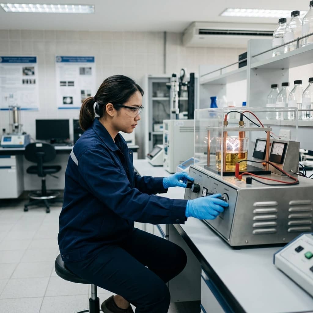
The post-overhaul SAT suite follows IEEE C57.152 guidance and the system owner's requirements: insulation resistance with polarization index, turns ratio at every tap, winding resistance on every phase and tap, Tan Delta of windings and bushings, exciting current, SFRA compared against the reference fingerprint to confirm no winding deformation from transport or repair, functional tests of every protection device, and a full oil analysis with DGA as the new baseline. Every result is systematically compared against pre-repair data and factory values before energization is approved.
Return to service is staged: energization at no load first, listening to the sound signature, checking exciting current, and closely watching protection relays through the first hour; then load is raised in steps while hot-spot temperatures and each cooling stage are verified. Scheduling follow-up DGA samples at 24 hours, one week, and one month after energization is good practice, since assembly-related defects typically reveal themselves as abnormal gassing in this early window. The enduring lesson of work at this scale: documentation of every step is worth as much as the craftsmanship itself, because it becomes the baseline the maintenance team will reference for the rest of the transformer's life.
Need engineering consultation regarding Transformer?
The WIN TECH SERVICE engineering team is ready to provide site surveys, electrical system inspections, and prepare accurate legal certification reports.