110V DC Battery Bank & Charger System Maintenance for Substations
📌 Executive Summary
Ensuring reliable DC backup power for trip coils, protective relays, SCADA, and motorized switchgear operation.
1. Why the 110V DC System Is a Substation's Lifeline
Every protection and control system in a substation — protective relays, breaker trip coils, switchgear drive motors, SCADA, and emergency lighting — runs on DC power from a battery bank supported by a charger. The critical reason: these systems are needed most during severe faults, exactly when the station's AC supply may sag or collapse. The energy source that trips a breaker in that second must be completely independent of the AC system.
This is why the station battery is called the lifeline of protection. If the battery has silently degraded, a relay may detect a fault while the breaker lacks the energy to open; the fault persists until a remote upstream device finally clears it, and damage spreads from one point to a wide area. Many serious substation failures worldwide have begun with a quietly failing DC system, making its maintenance as important as any primary high-voltage apparatus.
2. System Components, Battery Types, and Maintenance Standards
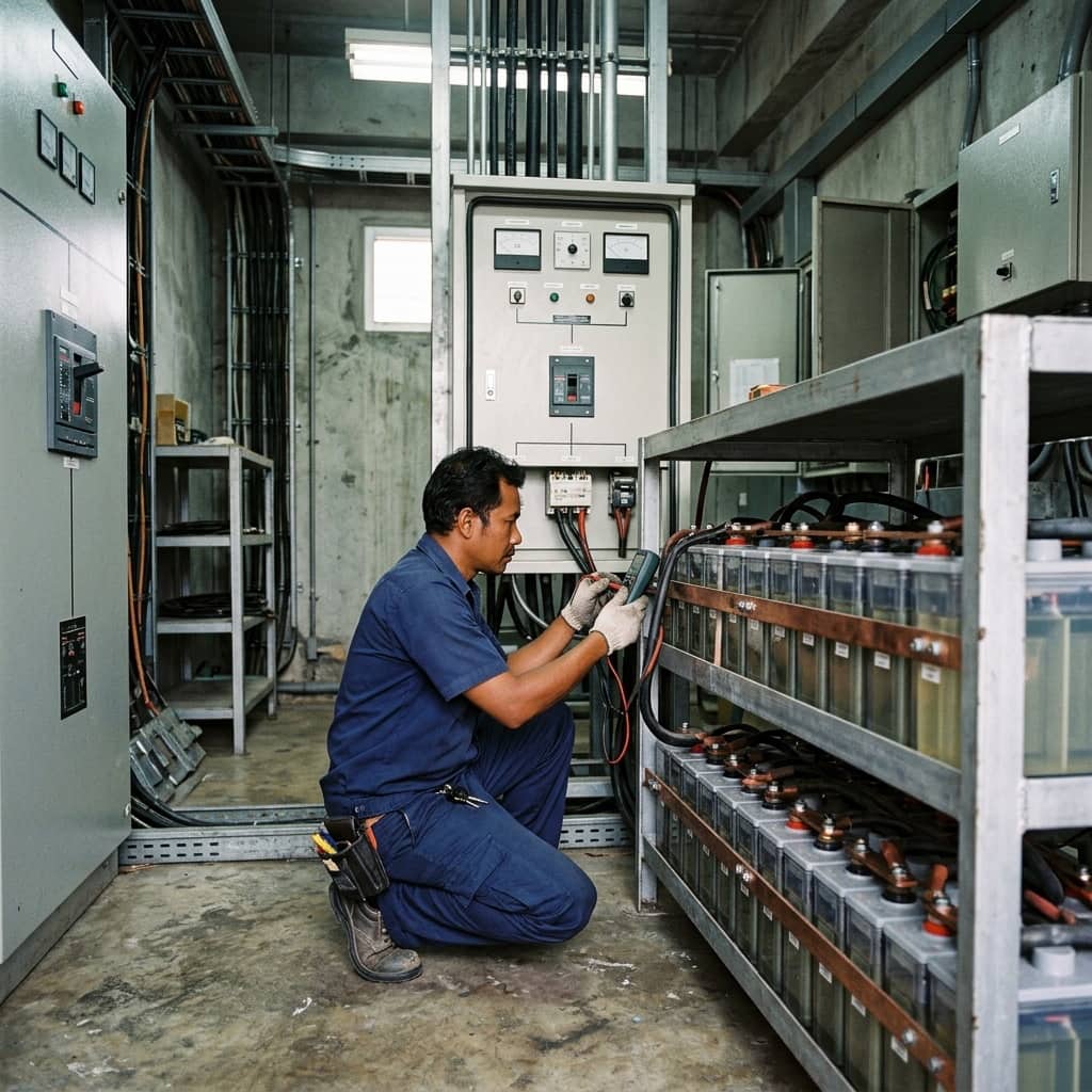
The system comprises series-connected cells forming the system voltage such as 110V DC, a charger carrying normal load while float-charging the battery, a DC distribution board with sub-breakers, and monitoring of voltage, current, and DC bus earth leakage. Two battery families dominate: valve-regulated lead-acid (VRLA), maintenance-free of watering but shorter-lived and temperature-sensitive, and vented (flooded) lead-acid or nickel-cadmium, longer-lived but requiring regular electrolyte level care.
Station battery maintenance practice follows IEEE standards — IEEE 450 for vented lead-acid and IEEE 1188 for VRLA — which define monthly, quarterly, and annual inspection items plus periodic capacity (discharge) testing. Recorded values include overall and per-cell voltage, float current, specific gravity for vented types, per-cell internal resistance or conductance, temperature, and terminal connection tightness.
- IEEE 450 — vented lead-acid battery maintenance and testing
- IEEE 1188 — recommended practice for VRLA batteries
- Log per-cell voltage, float current, and internal resistance
- Perform periodic capacity discharge tests
- Continuously monitor DC bus earth leakage
3. Inspection Routine and Capacity Testing Procedure
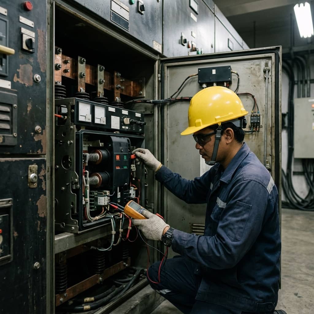
Routine inspection starts at the charger: read overall float voltage and charge current against the setpoint for the cell count and battery-room temperature — an abnormal rise in float current warns of failing cells or excessive temperature. Measure per-cell voltages to find outliers from the string average, inspect terminals for corrosion or salt deposits, re-torque to specification, and for vented types check electrolyte levels and measure pilot-cell specific gravity on schedule.
Capacity testing connects a load bank to discharge the battery at a specified constant current, timing until voltage falls to the end threshold; elapsed time versus design gives percent capacity. This is the only test that proves real battery capacity, and it demands careful planning because during the test the station depends on a backup DC source or temporary battery. It should be performed by an experienced team with a contingency plan in case a system fault occurs mid-test.
4. Degradation Signs to Watch and Extending System Life
Common findings include VRLA cells dried out by high battery-room temperatures, cutting life far below rating; terminal corrosion raising resistance and heating under high current; chargers set to the wrong float voltage causing chronic over- or under-charging; and DC bus earth faults from aged control wiring insulation — where two simultaneous faults can self-trip breakers or disable trip circuits. All of these are detectable in advance through consistent recording and trending.
Life-extension practice includes keeping the battery room within the manufacturer's temperature range, verifying the charger's temperature-compensated charging works correctly, clearing any earth fault immediately upon the first alarm, replacing the battery as a complete string once tested capacity falls below the standard-recommended threshold rather than mixing old and new cells, and rehearsing AC-failure scenarios to confirm the DC system truly carries its designed autonomy time — the ultimate guarantee that breakers will always have energy to trip when a real fault arrives.
- Heat is the number-one enemy of battery life
- Rising float current signals failing cells
- Clear DC earth faults immediately at the first alarm
- Replace batteries as complete strings — never mix old and new cells
Need engineering consultation regarding High Voltage?
The WIN TECH SERVICE engineering team is ready to provide site surveys, electrical system inspections, and prepare accurate legal certification reports.