Testing Metal-Oxide Surge Arresters (MOA) for Substation Safety
📌 Executive Summary
Measuring resistive leakage current and insulation resistance to detect thermal runaway risks in zinc-oxide surge arresters.
1. The Role of Metal-Oxide Surge Arresters in HV Systems
A Metal-Oxide Surge Arrester (MOA) limits transient overvoltages from lightning and switching so they never exceed what transformer, cable, and switchgear insulation can withstand. Its core is a stack of zinc-oxide (ZnO) varistor blocks with an extremely non-linear characteristic: at normal operating voltage only microamps to milliamps of leakage flow, yet during an overvoltage the arrester conducts surge currents of many kiloamps to earth within a fraction of a second.
Because an MOA is permanently energized, its varistor blocks degrade cumulatively from heat, moisture ingress into the housing, and the energy absorbed during each surge. This degradation appears as rising resistive leakage current, which generates internal heat and can escalate into thermal runaway, ending in violent arrester failure and an earth fault on the system. Periodic testing aims to detect this degradation trend at an early stage.
2. Relevant Standards and Key Parameters
The principal standard for metal-oxide arresters is IEC 60099-4, covering characteristics, testing, and classification of gapless arresters, with selection and application guidance in IEC 60099-5. Key parameters engineers must understand include rated voltage (Ur), maximum continuous operating voltage (MCOV/Uc), nominal discharge current, and the protection level, which must coordinate with the Basic Insulation Level (BIL) of the protected equipment.
In field condition assessment, the main indicators are total leakage current and its resistive component — especially the third harmonic of the resistive current, the parameter most sensitive to varistor degradation — together with housing insulation resistance and comparative thermographic scans, since a degraded phase runs visibly hotter than its neighbors.
- IEC 60099-4 — gapless metal-oxide arrester requirements
- IEC 60099-5 — selection and application guidance
- Coordinate protection level with equipment BIL
- Third-harmonic resistive leakage is the key degradation index
3. Offline and Online Arrester Testing Methods
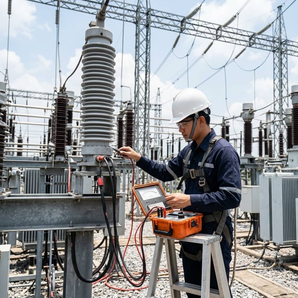
Offline testing begins by isolating the arrester, measuring housing insulation resistance with a high-voltage megohmmeter to screen for moisture, then measuring DC leakage current at the manufacturer-specified reference voltage — or the reference voltage at reference current — for comparison with factory data. Deviation beyond the manufacturer's limits indicates varistor degradation or internal moisture, and replacement should be planned before failure.
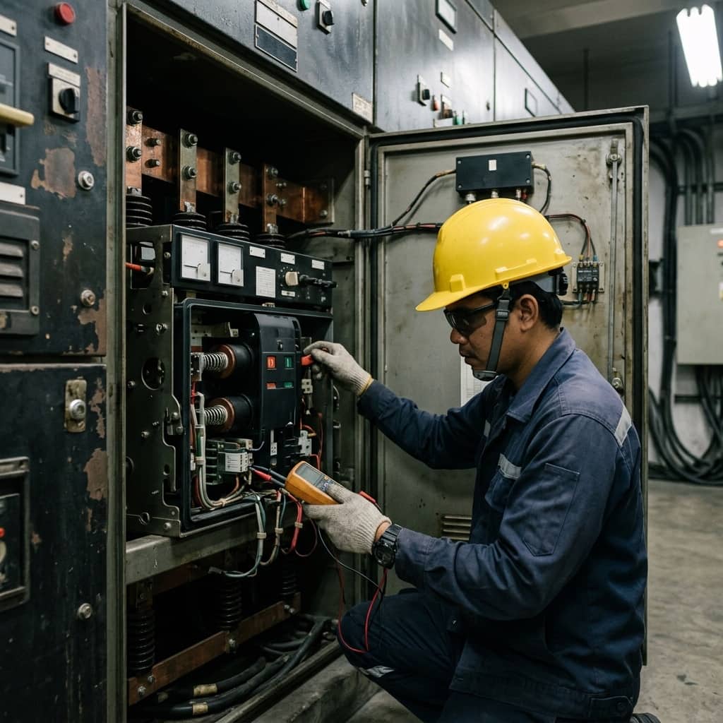
Online testing uses a leakage current instrument clamped around the arrester's earth lead, separating the resistive component from capacitive current through third-harmonic analysis. Because it requires no outage, it is well suited to trend-based monitoring. Ambient temperature and humidity must be logged at every measurement, since both significantly affect leakage readings, and successive readings should be taken under similar system conditions to remain comparable.
4. Degradation Warning Signs and Failure Prevention
Signs that an arrester is approaching end of life include a steadily rising resistive leakage trend, housing temperature higher than adjacent phases, unusually frequent surge counter operations during the lightning season, and external defects such as crazed polymer housings, degraded seals, or water staining at flanges — all of which give moisture a direct path to the varistor stack.
Prevention starts at design: select MCOV appropriate to the actual system voltage, particularly on impedance-earthed systems where healthy-phase voltage rises during earth faults. Fit disconnectors or surge counters to identify operated units, perform comparative thermal scans annually, and trend leakage current consistently. Once a clear degradation trend appears, replace the arrester at the earliest outage — an arrester failing violently in service endangers nearby equipment and personnel.
- A steadily rising leakage trend is the primary danger sign
- Compare housing temperatures between phases thermographically
- Match MCOV to the system earthing arrangement
- Replace degraded arresters at the first available outage
Need engineering consultation regarding High Voltage?
The WIN TECH SERVICE engineering team is ready to provide site surveys, electrical system inspections, and prepare accurate legal certification reports.