Maintenance of High Voltage Disconnecting Switches & Earthing Switches
📌 Executive Summary
Ensuring mechanical alignment, jaw contact pressure, simultaneous pole opening, and earthing interlock safety.
1. Function and Specific Risks of HV Disconnectors
A disconnector (isolator) provides a visible break for worker safety during maintenance, while an earthing switch solidly connects the isolated section to earth. Neither device is designed to interrupt load or fault current — operating one under load draws a severe arc that can escalate into a phase-to-phase fault and be lethal to the operator.
The specific risk profile of this equipment comes from infrequent operation combined with outdoor or dusty, humid locations: mechanisms stiffen, contacts oxidize, and blade alignment drifts unnoticed. When the switch is finally needed, often urgently, a neglected unit may fail to close fully, fail to open, or make insufficient contact pressure and overheat under continuous load — all preventable causes of accidents and outages addressed by scheduled maintenance.
2. Reference Standards and Acceptance Criteria
AC disconnectors and earthing switches are designed and tested to IEC 62271-102, which covers continuous current ratings, short-time fault withstand, and interlocking requirements between the earthing switch and the main blades. Installations on Thailand's 22–33 kV distribution and 115 kV sub-transmission systems must additionally comply with PEA or MEA technical requirements and the EIT electrical installation standard.
Condition criteria assessed during maintenance include per-pole contact resistance in micro-ohms compared across the three phases, simultaneity of three-pole engagement, blade penetration depth into the jaws per manufacturer dimensions, jaw spring pressure, free movement of the drive linkage through its full stroke, and correct operation of both mechanical and electrical interlocks that prevent earthing onto a live circuit.
- IEC 62271-102 — AC disconnectors and earthing switches
- PEA / MEA technical requirements for 22–115 kV systems
- Compare per-pole contact resistance across phases
- Verify simultaneity and blade penetration depth
- Function-test every interlock before return to service
3. Field Maintenance Procedure
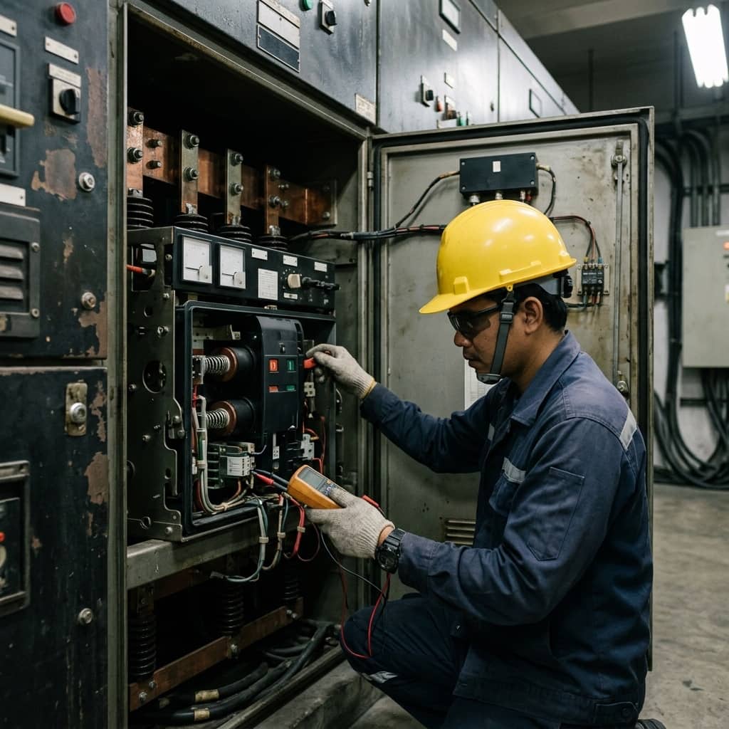
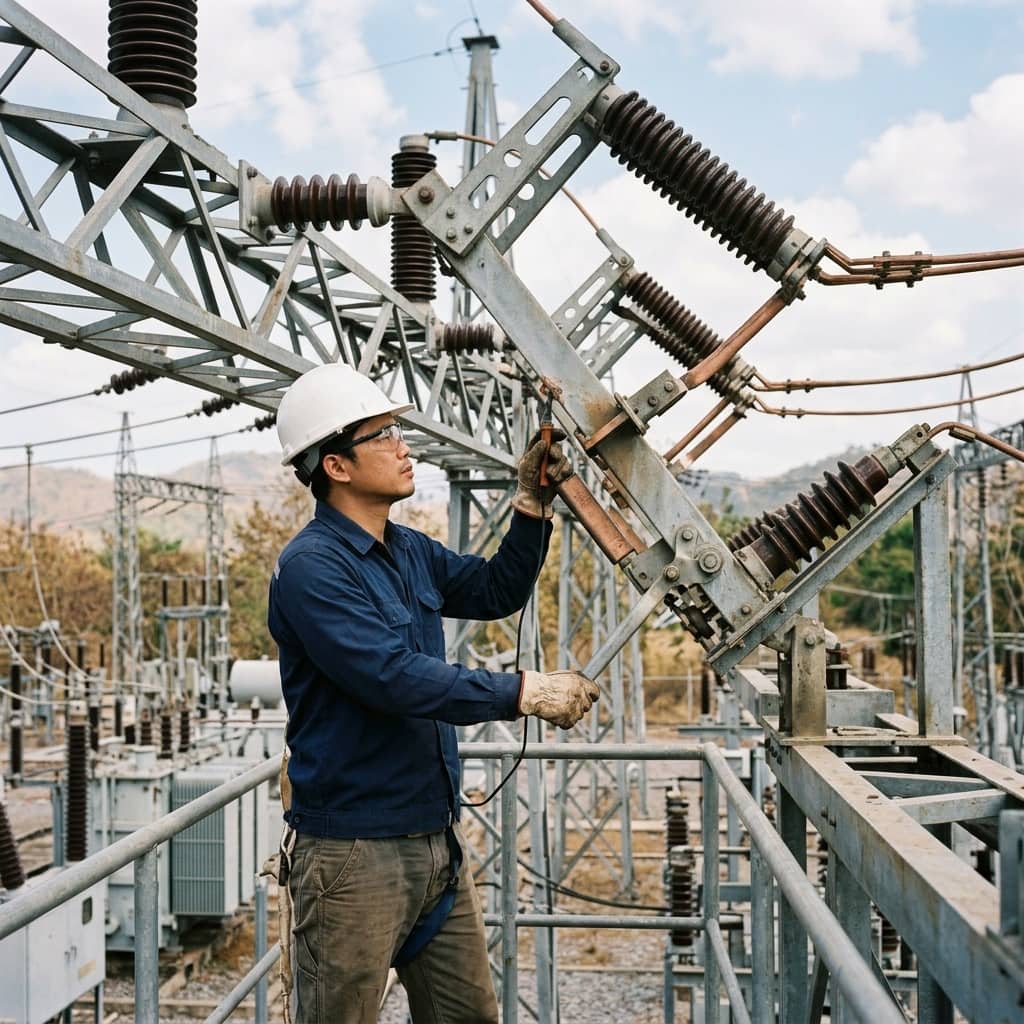
After isolation, verification of dead condition, and full application of earths, begin with a general inspection: post insulators must be free of chips, cracks, and tracking deposits. Clean blade and jaw contact surfaces using methods that preserve silver plating — coarse abrasives must never touch plated surfaces. Check jaw springs for fatigue or rust, then apply a thin, even coat of the manufacturer-specified conductive contact lubricant.
Operate the switch several times while observing all three poles, adjusting the drive linkage so the blades engage simultaneously and penetrate to the specified depth. Grease pivots and gear drives with lubricant suited to the installed environment, measure contact resistance with a micro-ohmmeter in the fully closed position, and finish by testing every interlock condition — key interlocks, anti-sequence mechanisms, and auxiliary contacts for remote control circuits — before removing earths and restoring the system per procedure.
4. Common Problems and Safety Lessons
The most frequent problem is contact overheating under load from insufficient jaw pressure or oxidized surfaces, usually caught by annual thermographic scanning. Next is a stiff mechanism preventing full closure, leaving inadequate penetration and abnormally high resistance. Most dangerous of all are interlocks that have been modified or bypassed because they once seemed inconvenient — opening the possibility of closing an earthing switch onto a live system, a severe accident that recurs in every era when discipline lapses.
Prevention means including every disconnector in the maintenance plan with no exemption for rarely used units, using load-condition thermography as a screening tool between overhauls, absolutely prohibiting interlock bypasses and verifying interlock integrity at each maintenance, training operators that these devices must never interrupt load, and mandating written switching procedures with breaker-status verification before every operation — so the visible break remains a genuine safety guarantee.
- Annual thermography screens for hot contacts
- Never bypass interlocks under any circumstances
- These devices must never interrupt load current
- Verify breaker status before every switching operation
Need engineering consultation regarding High Voltage?
The WIN TECH SERVICE engineering team is ready to provide site surveys, electrical system inspections, and prepare accurate legal certification reports.