Designing DC Fast Charging Infrastructure for Commercial Facilities
📌 Executive Summary
Transformer capacity planning, peak demand impact, cable sizing, and isolation transformers for multi-port DC chargers.
1. Power Delivery Principles for DC Fast Chargers
DC fast chargers rated from 60kW to 360kW differ fundamentally from ordinary AC chargers because the rectifier modules are located inside the charging cabinet rather than in the vehicle. A single cabinet can therefore draw several hundred amperes continuously from the low-voltage system. Electrical design must begin with an assessment of the peak demand of the entire station, not merely the nameplate rating of each unit, because real-world charging behavior frequently involves multiple connectors delivering full power simultaneously during rush periods.
A key consideration is the distribution transformer serving the station. As a rule of thumb, a site with two or more 150kW chargers usually requires a dedicated transformer from the utility so that the existing building load is not affected. Engineers must also account for the diversity factor and the charger efficiency (typically around 94-96%) when calculating input power, and verify that voltage drop along the feeder from transformer to charger remains within the limits required by the applicable standards.
- Assess peak demand from connectors that may operate simultaneously, not just the sum of ratings
- Include charger efficiency of roughly 94-96% when sizing input power
- Large stations should consider a dedicated utility transformer
- Keep feeder voltage drop from transformer to charger within standard limits
2. Applicable Standards for Fast Charging Stations
The principal standard governing DC charging systems is IEC 61851-23, which defines safety requirements for DC charging stations, together with IEC 61851-24 covering digital communication between the charger and the vehicle. Connectors and inlets follow the IEC 62196 series, with the CCS Combo 2 connector being the prevalent format in Thailand. Wiring and protective devices within the station must comply with the EIT (Engineering Institute of Thailand) electrical installation standard, including its dedicated chapter on electric vehicle supply equipment.
Beyond technical standards, operators must comply with the grid connection requirements of the Metropolitan Electricity Authority (MEA) or the Provincial Electricity Authority (PEA) depending on the service area. These cover meter upgrades, transformer installation, and power quality at the point of connection. Design by a licensed electrical engineer and a correct single line diagram are the baseline documents the utility uses when approving energization of the station.
3. Design and Installation Workflow
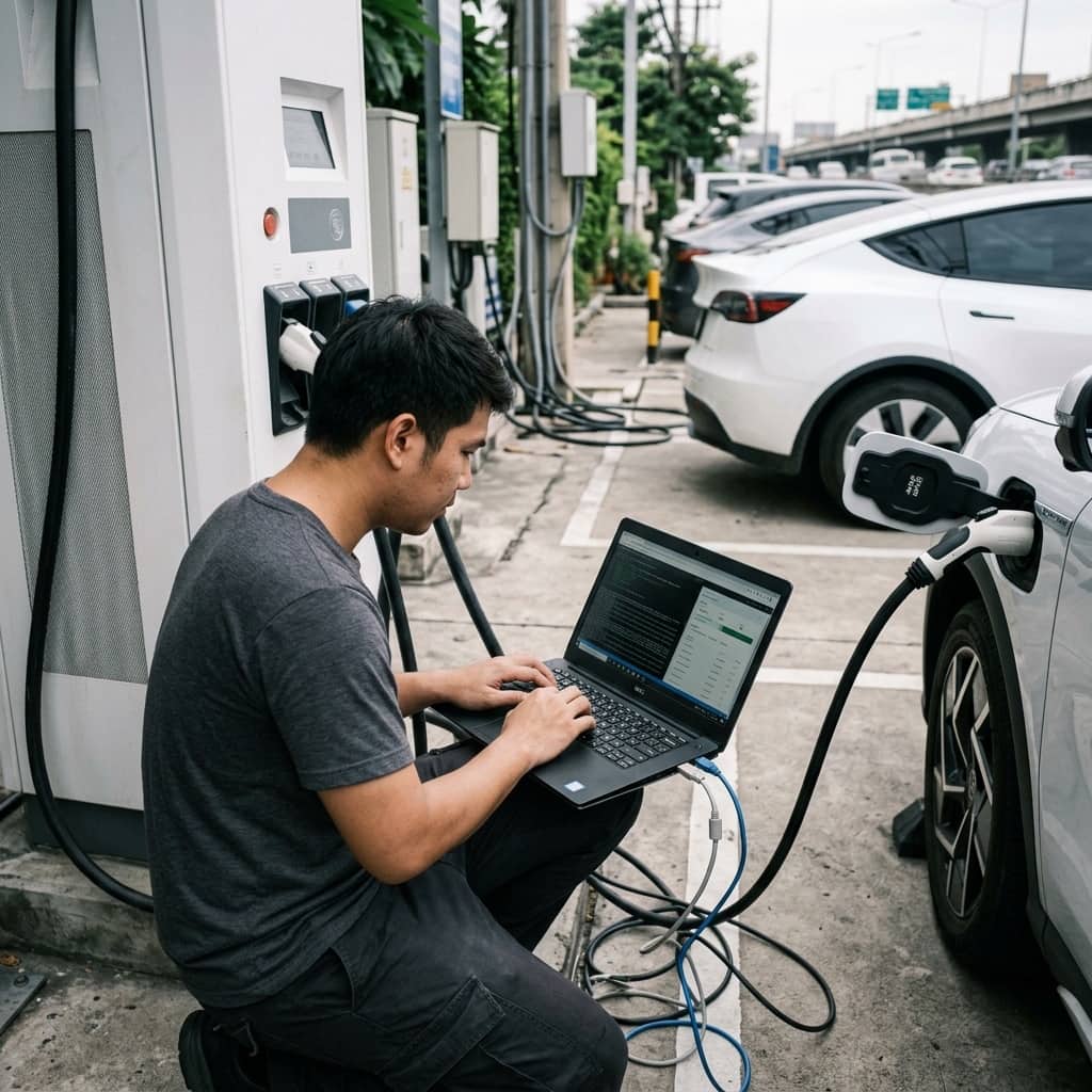
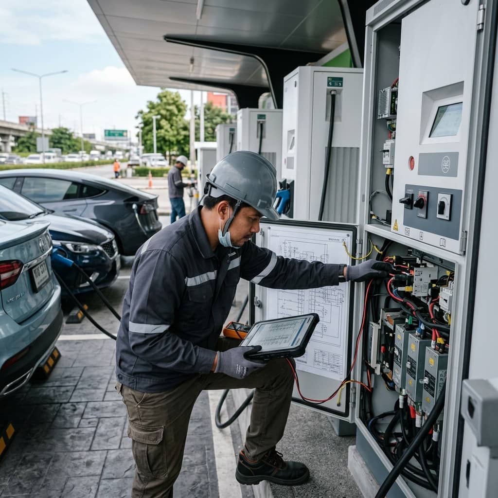
Installation begins with a site survey to establish the cable route from the transformer or main distribution board to the charger location. Feeder sizing must consider continuous current rating, installation method (underground conduit, cable tray, or busduct), and ambient temperature. A 150kW charger on a 400V system draws roughly 230-240A at the input, which typically requires large conductors or parallel runs, together with a dedicated circuit breaker whose breaking capacity (Icu) matches the prospective short-circuit current at the installation point.
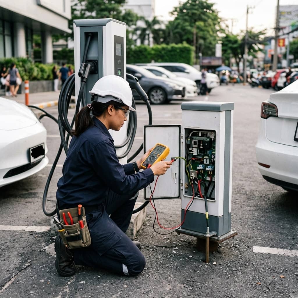
Civil and foundation work must allow for cabinet weights of several hundred kilograms up to over a tonne, plus ventilation clearances per the manufacturer's manual. After installation, pre-energization tests include insulation resistance, earth continuity, phase sequence, and verification of residual current protection. Commissioning then proceeds with an actual vehicle or a load simulator to confirm the insulation monitoring function and the standardized charge initiation sequence before the station enters service.
- Always measure insulation resistance and earth continuity before energization
- Verify phase sequence and residual current protection before service
- Commission with a real vehicle or load simulator
- Provide foundations and ventilation clearances per the manufacturer's manual
4. Common Problems and Preventive Measures
A frequent problem in DC fast charging stations is designing the transformer and feeders without allowance for future expansion. When operators later wish to add chargers, the entire system must be rebuilt at a much higher cost than provisioning it initially. Another issue is heat buildup in chargers installed in direct sunlight or with inadequate ventilation, causing the units to automatically derate and deliver slower charging speeds than advertised.
Preventive measures include planning modular infrastructure with spare conduits and transformer space for subsequent phases, selecting shaded installation locations or erecting canopies, and establishing a preventive maintenance plan covering air filter cleaning, torque-checking cable connections, and regular thermal scanning of critical joints. In addition, the charger's event log should be checked regularly, as minor anomalies like voltage imbalance often appear in the logs before escalating into a major outage.
Need engineering consultation regarding EV Infrastructure?
The WIN TECH SERVICE engineering team is ready to provide site surveys, electrical system inspections, and prepare accurate legal certification reports.