Dynamic Load Management (DLM) for Multi-Station EV Charging Fleets

📌 Executive Summary
Preventing factory main breaker overload by balancing available electrical capacity dynamically among active EV chargers.
1. Why Multi-Charger Sites Need Dynamic Load Management
When a building or factory adds multiple EV chargers to its existing electrical system, the first obstacle is that the spare capacity of the transformer and main breaker is rarely sufficient for all chargers to run at full power simultaneously. Without a control system, several vehicles charging at once during a period of high building load can push the total current past the breaker rating, tripping the main and blacking out the entire facility. Dynamic Load Management (DLM) was developed to share the actually available power among chargers in real time.
The system works by installing a CT meter at the building's main incomer to continuously read the total load. A central controller then computes the remaining headroom and adjusts each charger's current via control signals — for example by modulating the Control Pilot duty cycle per IEC 61851-1, or by commands over a communication protocol. When building load drops at night, the system automatically raises charging currents, extracting the full value of the transformer capacity without investing in an electrical system upgrade.
- Prevents main breaker trips when many vehicles charge at once
- Uses a CT meter for real-time monitoring of total building load
- Adjusts charging current via the IEC 61851-1 Control Pilot signal
- Allows more charge points without an immediate transformer upgrade
2. System Architecture and Communication Standards
DLM systems follow two main architectures. Local DLM uses an on-site controller communicating directly with chargers over a network such as Modbus TCP or a vendor-specific protocol; it responds quickly and keeps working even if internet connectivity is lost. Cloud-based DLM instead has the central management system (CSMS) impose power limits through the Smart Charging functions of OCPP, which suits operators managing many sites, but requires a carefully designed fallback profile for when connectivity drops.
In terms of standards, AC-side current control relies on the Control Pilot mechanism of IEC 61851-1, which defines the relationship between the PWM duty cycle and the maximum current the vehicle is permitted to draw. Cloud commands use the Charging Profile constructs of OCPP 1.6 or OCPP 2.0.1. A critical engineering check is each vehicle model's minimum accepted current: the standard sets the minimum charging current at 6A, and if the DLM pushes below that, some vehicles will stop charging entirely rather than charge more slowly.
3. Installing and Configuring a DLM System
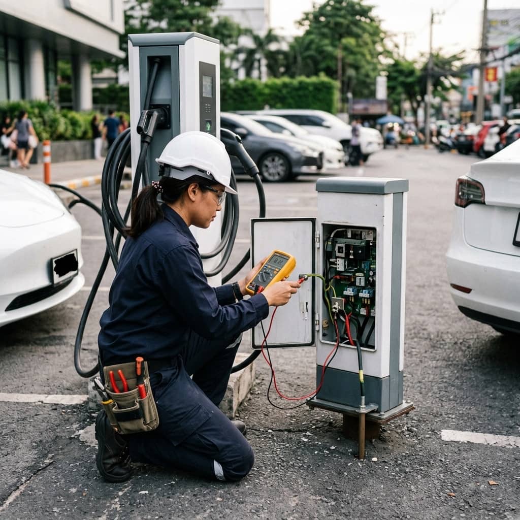
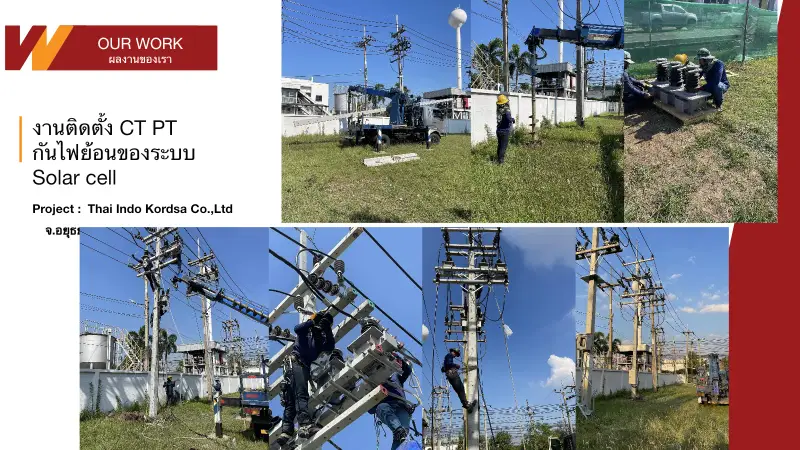
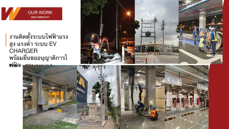
Installation starts with recording the building's load profile for at least seven days using a power quality logger, establishing peak load behavior across the day and defining a safe site power limit. CTs are then installed at the main incomer in a position that captures all loads including the EV circuits, and signal or LAN cabling is run to the controller and every charger — wired networking is recommended for control signals for reliability.
Configuration involves setting the site limit safely below the main breaker rating with an engineering margin, assigning charge point priorities (for example executive parking or delivery vehicles that must leave on schedule), and defining the failsafe current each charger falls back to if communication with the controller is lost. Acceptance testing should simulate worst-case conditions, such as plugging in every connector while the building runs at maximum load, and verifying by measurement that the total current at the main never exceeds the configured ceiling.
- Log the building load profile for at least 7 days before setting the site limit
- Set the site limit below the main breaker rating with a safety margin
- Assign charge point priorities and failsafe currents
- Test with all connectors charging at maximum building load
4. Frequent DLM Pitfalls in Operation
The most frequent mistake is installing CTs in the wrong position or orientation, causing the controller to misread building load and allocate more power than actually exists until the main breaker trips. Another failure mode is setting the failsafe current too high: when a network switch fails, every charger simultaneously reverts to its fallback current and the combined draw exceeds system capacity. Some vehicle models also respond poorly to current reduction, stalling the session so the user must replug.
Preventive measures include verifying CT orientation and ratio against a reference clamp meter on every phase before commissioning, setting failsafe currents conservatively based on the case where all chargers deliver simultaneously, maintaining a register of vehicle models regularly used at the site with tested responses to current adjustment, and periodically reviewing controller logs to catch abnormally frequent communication dropouts — usually an early sign of cabling or network switch problems before a real incident occurs.
Need engineering consultation regarding EV Infrastructure?
The WIN TECH SERVICE engineering team is ready to provide site surveys, electrical system inspections, and prepare accurate legal certification reports.