High Current Micro-Ohm Meter (Ductor Test) for Breakers & Busbar Joints
📌 Executive Summary
Using 100A DC injection to measure micro-ohm contact resistance across circuit breaker contacts and busbar joints.
1. Why Micro-Ohm Level Resistance Matters
Busbar joints, breaker contacts, and main cable lugs in a power system must carry hundreds to thousands of amperes through small contact areas, so their resistance must be extremely low — in the micro-ohm range (millionths of an ohm). If resistance rises by even a few tens of micro-ohms due to loosening, oxidation, or fatigued contact springs, I²R losses grow significantly: at 2000A, an extra 50 micro-ohms produces an additional 200 watts of heat at a single point.
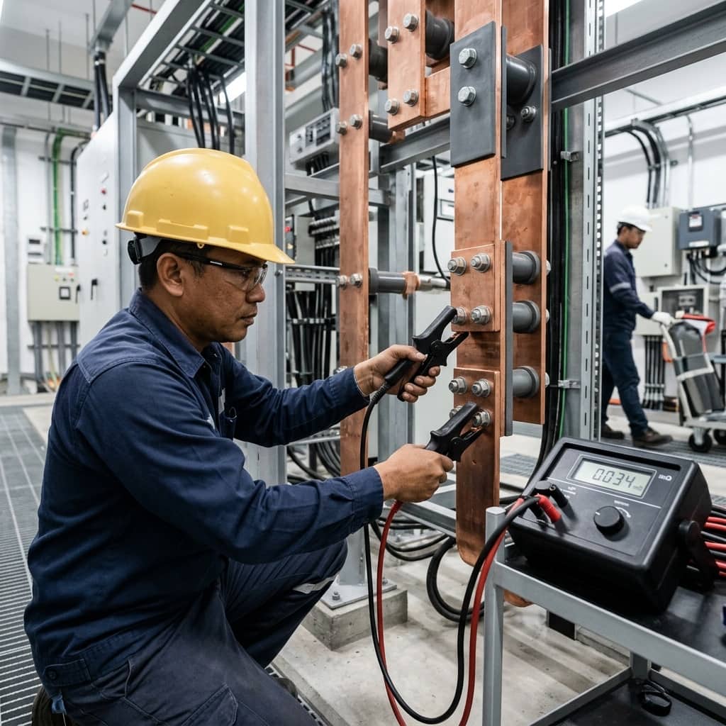
An ordinary multimeter cannot measure at this level because its own test-lead resistance is many times greater than the value of interest. A high-current micro-ohmmeter (Ductor) uses the Kelvin 4-wire principle: a high DC current such as 100A or 200A is injected through current terminals while a separate pair of potential leads measures the voltage drop, completely eliminating lead resistance from the result. The high current also replicates service conditions and breaks through thin oxide films better than low-current methods.
2. Evaluation Criteria and Reference Standards
The first yardstick is the equipment manufacturer's reference value — breaker manuals typically state a maximum contact resistance per model, ranging from tens to hundreds of micro-ohms depending on current rating. International acceptance-testing practice such as the NETA specifications adds a comparative rule: measured values across the three phases of the same device should be investigated when any pole deviates from the average by more than about 50%, even if the absolute value is still within specification.
Three comparisons should always be used together: against the manufacturer's specification, between phases, and against the same device's previous test results. A value creeping upward year after year, even while still passing, is evidence of progressive degradation — fatiguing contact springs or hardened conductive grease. Systematic record-keeping is therefore a precondition for getting full value from this test.
- Compare against the manufacturer's maximum for that specific model
- Compare between phases: deviation above ~50% from the average warrants investigation (NETA practice)
- Compare against history: a steadily rising value signals degradation
- Test at high current (e.g., 100A DC) to penetrate oxide films
- Document probe positions precisely so each survey measures identical points
3. Testing Breakers and Busbar Joints
Testing is performed with the equipment de-energized, fully isolated, and grounded per safety procedure. For a breaker, close it to the ON position and connect the current leads across the top and bottom terminals of each phase, always placing the potential leads inside the current leads. Inject current until the reading stabilizes and record each phase. For ACBs and VCBs, operate the breaker open-closed several times before measuring so the contact wiping action clears surface oxide — otherwise readings can be misleadingly high.
For busbar joints, measure across each joint with the potential leads placed at a fixed, documented distance on either side so results are comparable between surveys. The reading includes both bar material and the joint; any joint measuring clearly higher than identical joints elsewhere is the one to open and inspect. The test should also be repeated after any re-torquing or new busbar assembly to verify workmanship before re-energizing.
4. Common Defects and Remedies
The most common busbar-joint defect is incorrect bolt torque, whether from original assembly or loosening under thermal cycling. Poorly prepared contact surfaces come next — aluminum oxide not removed before assembly, or unsuitable joint compound. In breakers, typical findings are eroded arcing contacts, fatigued contact springs, and mechanisms loosened by repeated fault interruptions.
An out-of-limit busbar joint is remedied by disassembly, surface inspection, cleaning, application of the correct joint compound for the metal type, and reassembly with a torque wrench and spring washers to specification. A breaker with high contact resistance requires overhaul or contact replacement per the manufacturer's manual. In every case, re-measure after the repair to confirm the value is back within limits and record it as the new baseline for the next survey.
Need engineering consultation regarding Preventive Maintenance?
The WIN TECH SERVICE engineering team is ready to provide site surveys, electrical system inspections, and prepare accurate legal certification reports.