Copper Busbar Sizing & Temperature Rise Calculation in Main Distribution Boards
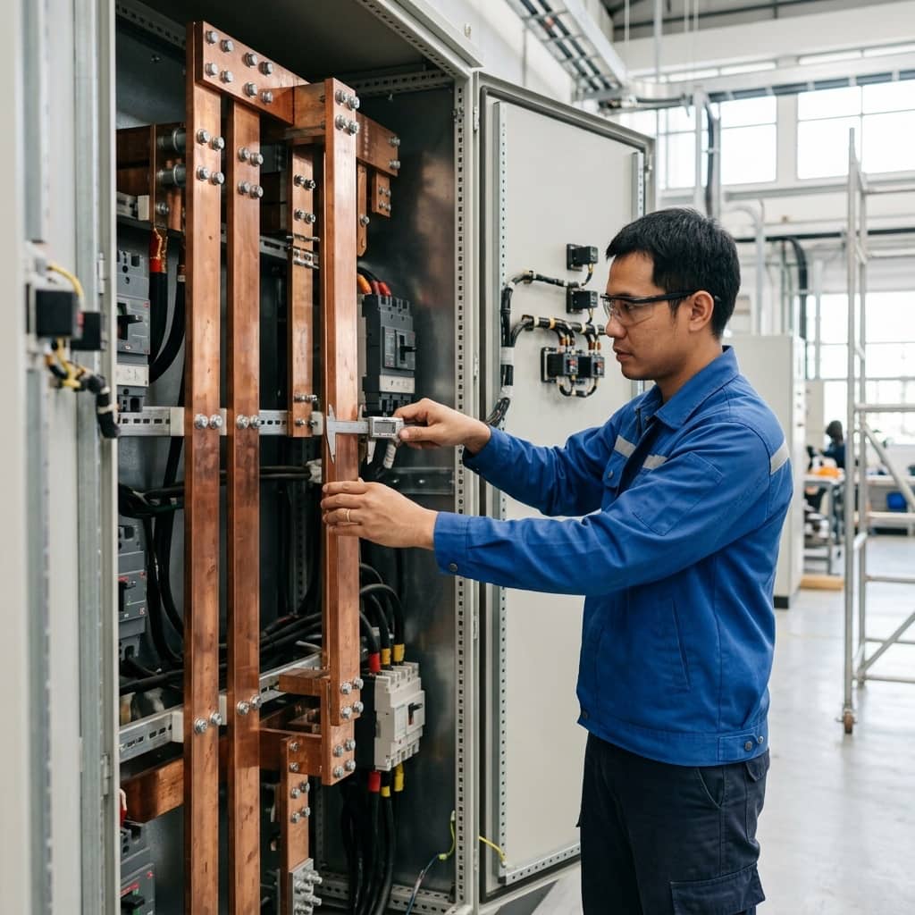
📌 Executive Summary
Selecting busbar cross-section area, skin effect factor, surface plating, and phase clearance according to DIN 43671 standards.
1. Fundamentals of Copper Busbar Ampacity
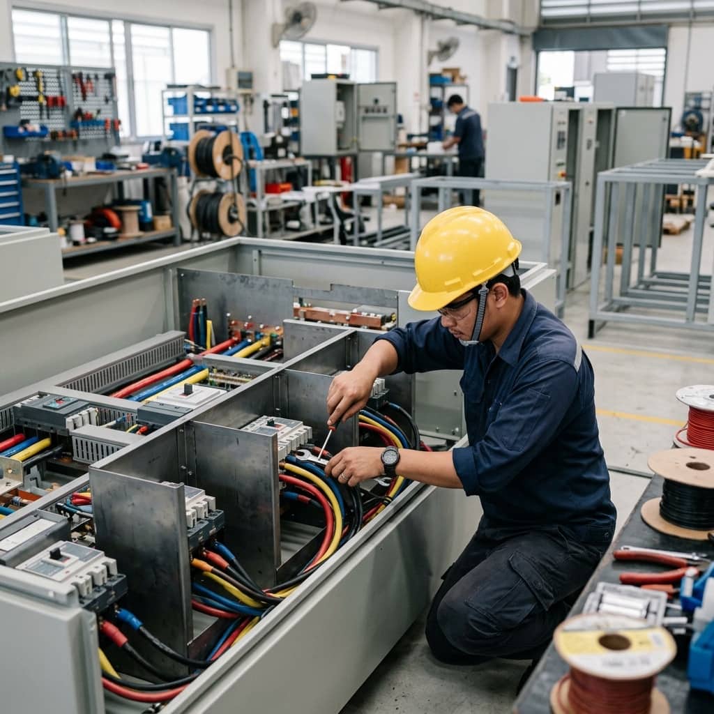
Copper busbars are the main current paths inside an MDB, carrying power from the main breaker to the outgoing circuits. Continuous ampacity depends not on cross-sectional area alone but on the balance between I²R heat generation and heat dissipation to the surrounding air by convection and radiation. Key factors therefore include the bar's width-to-thickness ratio, vertical or horizontal orientation, the number of bars per phase, inter-bar spacing, and the ambient temperature inside the enclosure.
At 50 Hz, skin effect concentrates current near the surface rather than the core, and when several bars run in parallel per phase, proximity effect makes the current share between them unequal. Two parallel bars therefore do not carry twice the current of one. Designers must apply derating factors from standard tables rather than simple multiplication, or the busbar will overheat despite an apparently adequate cross-section.
2. Using DIN 43671 Tables and Temperature-Rise Limits
The most widely referenced standard for copper busbar sizing is DIN 43671, which tabulates ampacity for standard rectangular sections at reference conditions: 35 degrees Celsius ambient, 65 degrees Celsius conductor temperature, still indoor air. Values are given separately for bare and painted surfaces (painted bars radiate better and carry more current) and for one to several parallel bars per phase.
Where actual conditions differ, correction factors apply — higher enclosure ambient than 35 degrees, altitude, or installation in a poorly ventilated enclosure. Furthermore, the temperature-rise limits of the complete assembly must comply with IEC 61439-1, which caps temperatures at terminals and devices so that insulation, joints, and neighbouring equipment do not age prematurely. Busbars inside real enclosures therefore usually end up larger than the raw DIN table values suggest.
- DIN 43671 reference conditions: 35°C ambient, 65°C conductor, still air
- Painted bars carry more current than bare bars due to better radiation
- Apply derating factors for multiple parallel bars per phase
- Correct further when enclosure ambient exceeds the reference
- Always verify overall assembly temperature rise per IEC 61439-1
3. Short-Circuit Withstand and Support Spacing Checks
Beyond continuous current, busbars must withstand short circuits both thermally and mechanically. Thermally, the cross-section must keep the conductor below its short-time temperature limit for the full breaker clearing time (the Icw rating at a stated duration such as 1 second). Mechanically, the peak fault current produces enormous electromagnetic forces between phases that try to push the bars apart — forces proportional to the square of the current and inversely proportional to phase spacing.
Support spacing is therefore a critical design variable: closer supports mean lower bending moments in the bars. Busbar supports must carry mechanical ratings consistent with the system's peak fault current. For design-verified assemblies, the enclosure manufacturer publishes matched tables of bar size, support spacing, and Icw rating which the panel builder must follow strictly — support spacing cannot be stretched to save on insulators.
4. Busbar Joints: The Overlooked Heat Source
Most field overheating problems are not caused by undersized bars but by joints, where contact resistance rises over time as bolt torque relaxes through thermal cycling, contact surfaces oxidise, or unsuitable washers are used. A degrading joint heats itself in an accelerating spiral that can end in melting and an internal arc. Excessive drilling at joints also reduces the net cross-section at that point.
Good practice is to prepare contact surfaces flat and clean before assembly, tighten bolts to specified torque with disc-spring or pressure-retaining washers, apply torque marks so loosening is visible at a glance, and include thermal imaging under high load in the annual maintenance plan — comparing each joint against its neighbours and against the previous year's results. Any joint trending clearly hotter than normal must be opened, inspected, and remade before it reaches a critical state.
- Prepare joint surfaces flat and clean before every assembly
- Torque with a calibrated wrench, disc-spring washers, and torque marks
- Thermally image joints under high load every year
- Open and remake any joint trending abnormally hot without delay
Need engineering consultation regarding Low Voltage & MDB?
The WIN TECH SERVICE engineering team is ready to provide site surveys, electrical system inspections, and prepare accurate legal certification reports.