Arc Flash Hazard Analysis & PPE Category Assessment (IEEE 1584 Standard)
📌 Executive Summary
Calculating incident energy levels (cal/cm2), arc flash boundaries, and establishing proper Personal Protective Equipment (PPE) requirements.
1. Understanding the Arc Flash Hazard
An arc flash is the violent energy release when fault current flows through air between conductors, creating an extremely high-temperature plasma in a fraction of a second, together with a pressure wave, hearing-damaging sound, molten metal spray, and blinding light. A worker standing at the panel can suffer fatal burns without ever touching a live part. Common triggers are working on energised equipment, dropped tools bridging busbars, animal ingress, and degraded insulation.
Severity at a given location is not primarily a function of voltage, as often assumed, but of incident energy — determined by the actual arcing current, the working distance from the arc, and above all the duration the arc persists before the protective device clears it. A low-voltage board with high fault current and a long upstream time delay can be more dangerous than a higher-voltage system whose protection clears quickly.
2. The IEEE 1584 Calculation Framework
IEEE 1584 is the most widely used arc flash calculation standard; the 2018 edition builds its model on an extensive test programme. Key variables include bolted fault current, system voltage, conductor gap, electrode configuration inside the enclosure, enclosure dimensions, and working distance. The calculation first derives the arcing current, which is lower than the bolted value, reads the clearing time from the upstream protective device's curve at that current, then computes incident energy in calories per square centimetre.
Critically, the standard requires repeating the calculation at the reduced arcing current, because a lower arc current can shift the operating point into a longer-delay region of the breaker curve, producing higher total energy than the full arcing current case. The results yield both the incident energy at the working distance and the arc flash boundary — the distance at which energy falls to the second-degree-burn threshold — which defines the approach limit for anyone without protective equipment.
3. PPE Selection and Equipment Labelling
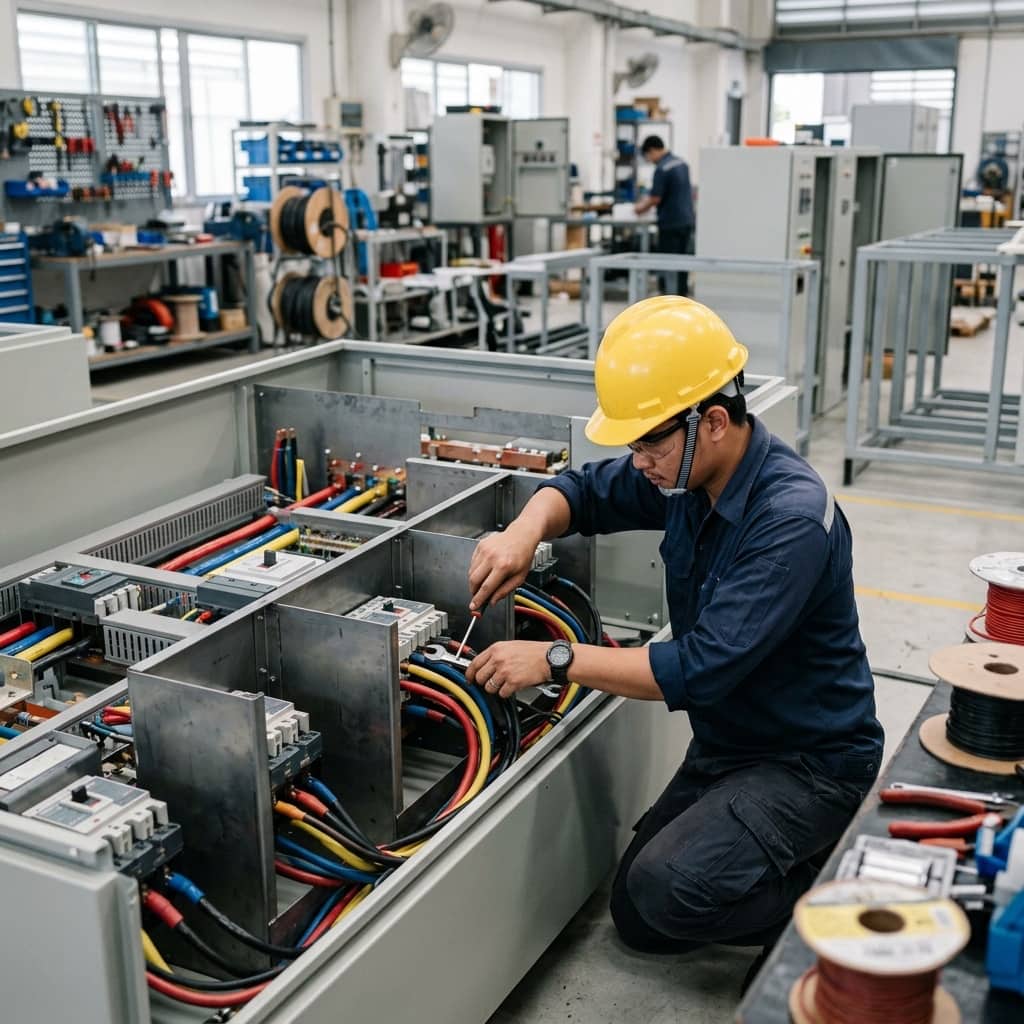
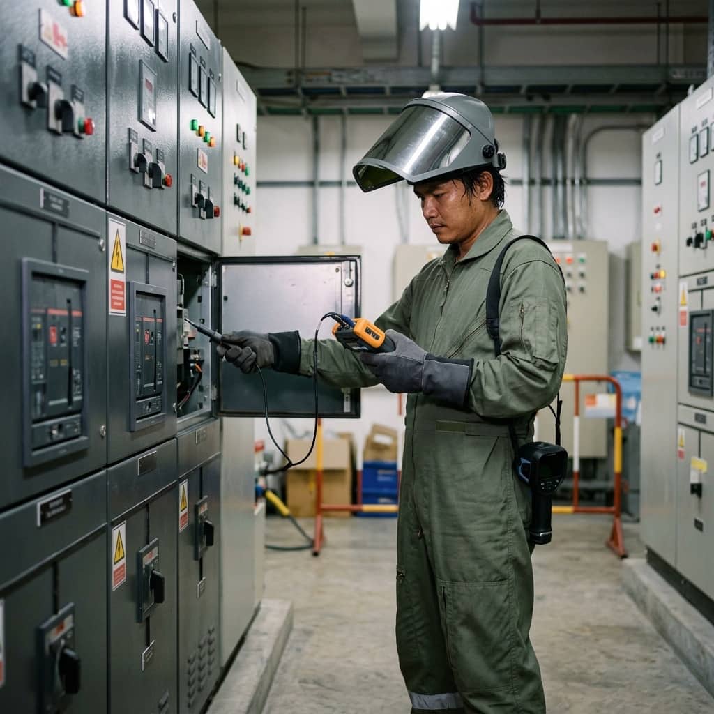
The calculated incident energy drives the selection of arc-rated PPE: the clothing worn must have an arc rating (ATPV) not less than the incident energy at that working point. Workplace electrical safety practice such as NFPA 70E groups PPE into categories, from basic arc-rated fabric with a face shield up to full suits with hoods for high energies, always accompanied by appropriate gloves, footwear, and hearing protection.
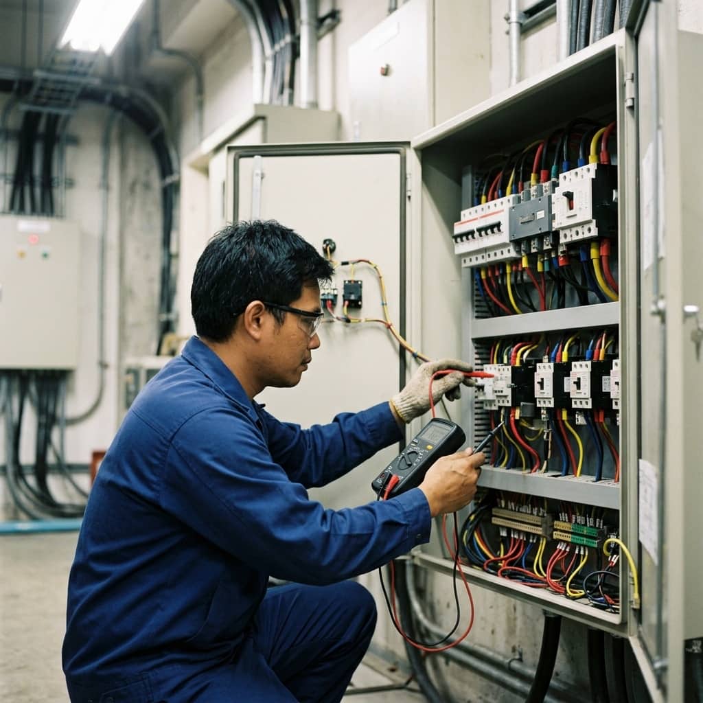
Study results must be translated into labels on each panel showing incident energy with its reference working distance, the arc flash boundary, the required PPE, and system voltage, so workers can decide at the equipment without consulting the report. It must always be stressed that PPE is the last resort in the hierarchy of controls — the superior measure is de-energising and verifying absence of voltage under lockout/tagout, which removes arc flash exposure from most work entirely.
- Select clothing with an arc rating (ATPV) at or above the calculated incident energy
- Panel labels must show energy, working distance, boundary, and required PPE
- PPE is the last resort — de-energise and verify absence of voltage first
- Do not omit gloves, footwear, and hearing protection per the hazard level
4. Practical Arc Energy Reduction Measures
Because incident energy is directly proportional to arc duration, the most effective mitigations shorten clearing time: a maintenance mode switch that temporarily engages a low instantaneous setting while personnel work at the panel; arc flash relays combining light and current detection to trip within milliseconds; zone selective interlocking that lets the breaker nearest the fault clear fast without inherited coordination delays; and reviews of time delays set longer than necessary.
Common failings are performing the arc flash study once and never updating it — although transformer changes, breaker setting revisions, or added sources all change the results; posting generic labels that do not match the actual study; and the misconception that PPE licenses energised work in all cases. Correct practice updates the study when the system changes or at the interval good practice prescribes, trains workers to read labels and assess tasks, and builds a culture where de-energised work is the default, not the exception.
- Use a maintenance mode switch to shorten arc time during panel work
- Consider arc flash relays combining light and current detection
- Review breaker time delays set longer than necessary
- Update the arc flash study whenever the system changes
Need engineering consultation regarding Low Voltage & MDB?
The WIN TECH SERVICE engineering team is ready to provide site surveys, electrical system inspections, and prepare accurate legal certification reports.