Solar-Assisted EV Charging Hubs with Battery Storage Buffer
📌 Executive Summary
Using rooftop solar arrays and BESS buffer batteries to supply peak DC fast charging power without expanding grid utility connections.
1. The Solar-Plus-Storage Charging Hub Concept
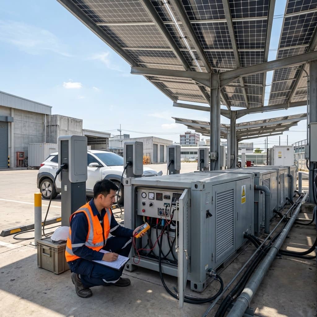
The major constraint on expanding fast charging is the capacity of the local distribution network. Transformer upgrades or new utility feeders take substantial time and capital. The solar EV charging hub concept combines two sources: rooftop or solar carport arrays accumulate energy into a battery energy storage system (BESS) throughout the day, and the battery then acts as a buffer supplying short bursts of high power alongside the grid whenever a vehicle fast-charges.
The underlying principle is that fast charging load is high-peak but short-duration, while solar production is a daytime curve that rarely aligns with those peaks. The buffer battery converts energy produced across the whole day into high power delivered exactly when needed, letting a limited grid connection support chargers rated above the feeder capacity. The approach is especially suited to areas where the distribution system is saturated, or to businesses with large roof areas seeking to cut peak-period electricity costs at the same time.
2. Standards and Interconnection Requirements
A grid-parallel solar system must comply with the MEA or PEA grid connection code, which covers inverter characteristics, anti-islanding protection, and the approval process for paralleling a generating source. The DC side of the array follows the Thai electrical installation standard and the EIT's dedicated solar installation standard, including lightning protection and earthing of the module support structures.
For the storage system, battery selection should weigh cell- and system-level safety certification aligned with international standards such as the IEC 62619 series for industrial batteries, together with a battery management system (BMS) that disconnects on abnormal parameters. BESS enclosures need clearances for heat dissipation and firefighting access, and when co-located with buildings the arrangement should be discussed with local authorities and insurers as with any large system, since siting requirements for BESS continue to evolve.
3. System Sizing and Microgrid Architecture
Sizing starts with the station's projected usage profile — sessions per day, their time distribution, and average energy per session — matched against the site's hourly solar production curve to balance array size, battery capacity (kWh), and battery power rating (kW). A common misconception is conflating capacity with power: a high-capacity but low-power battery cannot buffer a fast charger, so the system's continuous C-rate must be verified against the real peak.
Common architectures are AC-coupled, where solar, battery, and chargers all connect through a common AC bus — flexible and built from standard equipment — and DC-coupled, integrating everything on a DC bus to remove conversion stages and raise overall efficiency. The energy management system (EMS) is the brain deciding what proportion of charging load is served from solar, battery, or grid, aiming both to keep grid draw under the ceiling agreed with the utility and to husband battery cycling for economic life.
- Distinguish clearly between battery capacity (kWh) and power rating (kW)
- Verify continuous C-rate against the chargers' real peak demand
- Choose AC-coupled or DC-coupled architecture per project context
- The EMS must keep grid draw under the ceiling agreed with the utility
4. Field Lessons and Long-Term Care
Frequent problems include overestimating solar yield by neglecting module soiling, shading from adjacent structures, and the high module temperatures of the Thai climate that reduce output — leaving less energy in the battery than planned and greater grid dependence than expected. Batteries also degrade faster than warranted when the EMS is configured for overly frequent deep cycling, or when the enclosure sits where hot air accumulates and the cooling system runs continuously.
Long-term care should track monthly indicators: actual versus estimated production, battery state of health, and the share of load energy served by each source. Schedule panel cleaning according to the site's real dust conditions, test anti-islanding protection and disconnection devices on the utility's prescribed cycle, and revisit the EMS dispatch strategy annually as usage patterns evolve — a station with growing traffic will always need its source balance re-tuned.
- Track actual yield versus estimate and battery state of health monthly
- Schedule panel cleaning by real site dust conditions
- Test anti-islanding on the utility's prescribed cycle
- Revisit the EMS dispatch strategy annually as usage evolves
Need engineering consultation regarding EV Infrastructure?
The WIN TECH SERVICE engineering team is ready to provide site surveys, electrical system inspections, and prepare accurate legal certification reports.