Electrical Substation Design for Commercial Electric Bus & Truck Fleets
📌 Executive Summary
High voltage dedicated transformer substations (115kV/22kV), megawatt-scale power demand, and harmonic mitigation for logistics depots.
1. The Engineering Challenge of Electric Bus and Truck Depots
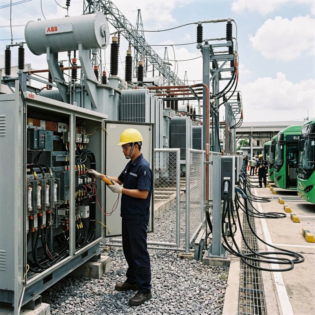
A commercial EV fleet depot operates on an entirely different power scale from passenger car charging. A single electric bus carries a battery of several hundred kilowatt-hours, and a depot with dozens of vehicles must complete charging within a nighttime window of a few hours, driving total demand into the multi-megawatt range. This exceeds ordinary low-voltage systems and typically requires supply from the 22kV distribution network, or in some cases a substation-level connection from the 115kV system.
The core of the design is charging schedule simulation against the vehicle duty roster to find the true peak demand — vehicles do not all return simultaneously, nor must they charge at full power throughout. Intelligent charge sequencing can significantly reduce the required transformer capacity. The simulation output becomes the basis for grid connection negotiations with the utility, transformer count and sizing decisions, and planning around demand charges, which are a dominant operating cost of the depot.
2. Substation and High-Voltage System Design
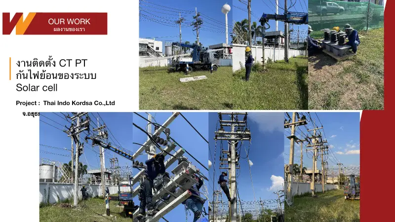
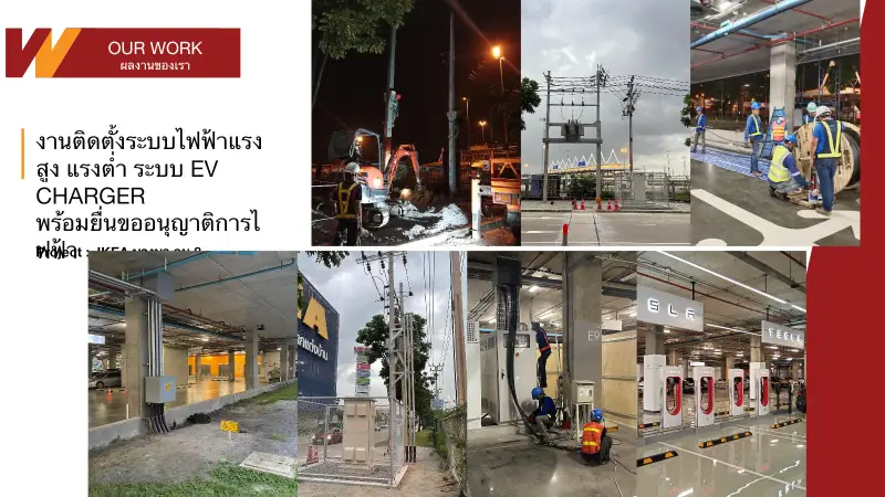
A multi-megawatt depot generally requires a dedicated transformer station comprising 24kV switchgear or ring main units, one or more power transformers, and low-voltage main boards feeding charger groups. Splitting capacity across several transformers rather than one large unit limits the impact of a single failure and supports phased construction as the fleet grows. Protection must be coordinated from the high-voltage relays down to each charger's branch breaker, supported by a short-circuit study of the whole system.
Grid connection must satisfy the PEA or MEA connection code, which governs power quality at the coupling point — particularly harmonics from many DC charger rectifiers operating simultaneously. A harmonic study and reserved space for active harmonic filters should be part of the design stage. The depot layout must also keep the wide turning paths of buses clear of high-voltage cable pits and transformer positions, for both safety and long-term maintainability.
- Simulate the charging schedule before sizing transformers to avoid over-investment
- Split capacity across multiple transformers for resilience and phased growth
- Perform protection coordination and a system-wide short-circuit study
- Run a harmonic study and reserve filter space at design stage
- Keep bus turning paths clear of HV cable routes and transformers
3. In-Depot Distribution and Fleet Charging Technology
Within the depot, distribution from main boards to long rows of bays is commonly done with busduct or cable ladder runs parallel to the parking rows, avoiding an enormous number of individual feeders. Fleet charging hardware includes power cabinet architectures — rectifier stacks centralized in an electrical room feeding multiple slim dispensers at the bays, saving space and simplifying maintenance — and pantograph systems for buses requiring rapid connection without handling cables. Selection depends on the vehicle manufacturer's specifications and the operating pattern.
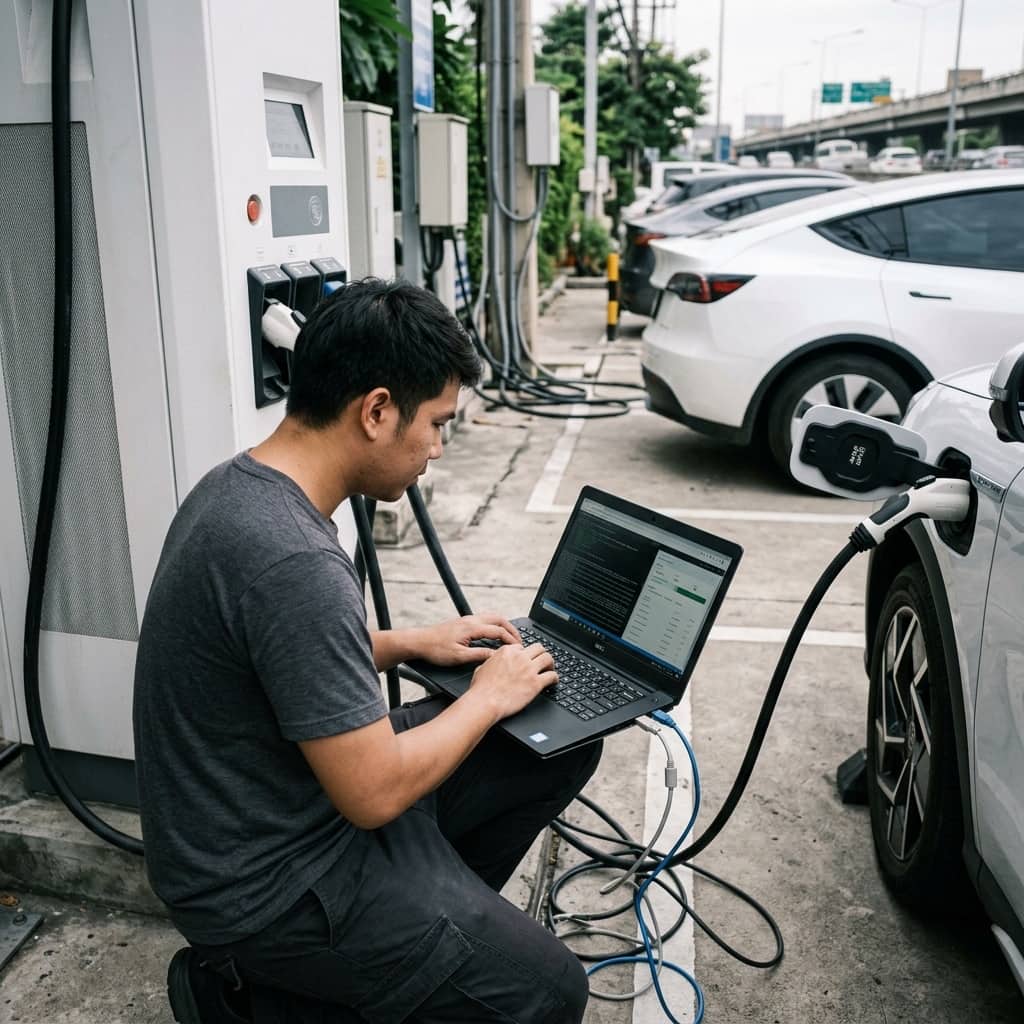
The charging management system is the layer binding everything together: sequencing charging against the departure timetable, allocating power within the planned demand ceiling, and integrating each vehicle's battery state. Depot acceptance testing should include realistic scenarios — the full fleet returning and charging on schedule — verifying that total demand stays within the utility contract and that the system still prioritizes vehicles with the earliest departures correctly when power is constrained.
4. Operational Risks and Management Approaches
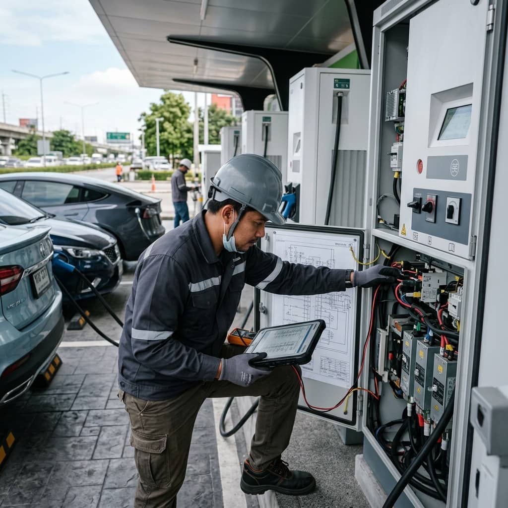
The dominant risk in a fleet depot is availability: one failed charger can mean several vehicles missing service the next morning. Frequent problems include heat buildup in rectifier rooms from inadequate ventilation, dust-clogged filters causing derating, demand charges exceeding plan due to off-schedule charging when vehicles return late, and dispenser wear from multiple heavy cycles per night.
Management approaches include designing redundancy into both dispenser count and distribution paths so operations continue during equipment repairs, maintenance contracts with defined response times from the charger manufacturer, real-time monitoring with alarms for electrical room temperature and charger status, and monthly reviews of actual load data against plan to refine the schedule. Training drivers and depot staff in correct plug-in procedure and fault reporting also reduces usage-related failures to a surprising degree.
- Design redundancy in both dispenser count and distribution paths
- Contract maintenance with defined response times
- Monitor electrical room temperature and charger status in real time
- Review actual load against plan monthly to refine the schedule
Need engineering consultation regarding EV Infrastructure?
The WIN TECH SERVICE engineering team is ready to provide site surveys, electrical system inspections, and prepare accurate legal certification reports.