EVSE Testing Adapters & Periodic Maintenance Inspections
📌 Executive Summary
Using EVSE simulators to test Control Pilot (CP) and Proximity Pilot (PP) communication states A, B, C, and D prior to handoff.
1. Why EV Chargers Require Dedicated Test Instruments
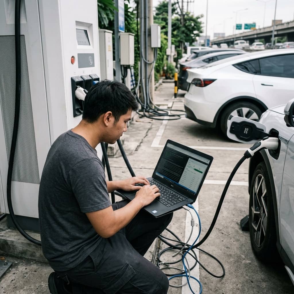
An EV charger differs from ordinary electrical equipment in that it only delivers power after successfully negotiating with the vehicle over the Control Pilot (CP) and Proximity Pilot (PP) signals per IEC 61851-1. Generic electrical instruments can verify the supply circuit up to the unit, but cannot confirm that it will actually energize for a vehicle, disconnect on genuine leakage, or advertise current limits correctly. The EVSE tester (EV simulator adapter) is therefore the primary instrument for acceptance and maintenance work, standing in for the vehicle and simulating every connection state.
Such testers plug into the Type 2 or other IEC 62196 connector and emulate the vehicle's standardized circuit states: state A (unplugged), state B (connected but not ready), and state C (ready to receive power), while measuring the PWM signal the unit advertises to confirm the permitted current ceiling. More complete models add fault simulation — AC and DC leakage injection, broken protective earth, and CP short-circuit — verifying that the charger responds by disconnecting within the times the standard requires.
2. The Standards-Based Annual Test Checklist
Annual verification should follow the periodic re-inspection principles of IEC 60364-6 together with the EV-circuit requirements of IEC 60364-7-722. On the supply side: insulation resistance, protective conductor continuity, earth fault loop impedance, and testing of every RCD with an instrument recording both trip current and trip time. Where the circuit relies on a Type A RCD combined with an in-unit RDC-DD, the 6mA DC leakage detection must be tested with a dedicated simulator, because the external RCD's test button does not exercise that function.
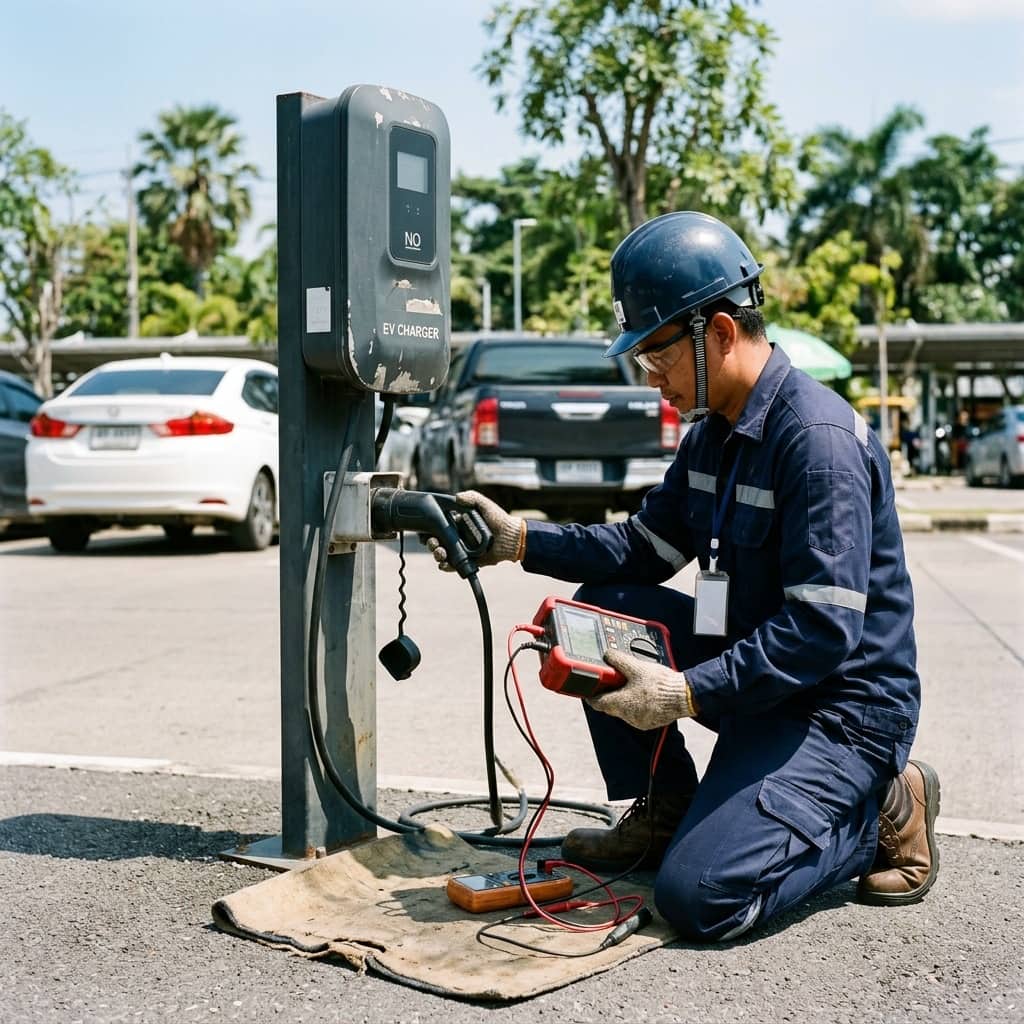
On the charging-function side, the EVSE tester works through the sequence: A-B-C state transitions and energization in state C, PWM duty cycle measured against the unit's rating, a simulated broken earth during charging which must cause immediate disconnection, and the emergency stop button where fitted. The inspection closes with mechanical condition — connector, contacts, cable, cabinet fixings, and weather seals. Every result should be recorded against the previous year's values to track degradation trends, not merely judged pass or fail in isolation.
- Test every RCD, recording trip current and trip time
- Verify 6mA DC leakage detection of the RDC-DD with a dedicated simulator
- Check A-B-C state transitions and measure the CP duty cycle
- Simulate broken earth during charging; the unit must disconnect immediately
- Record results against prior years to track degradation trends
3. Safe Field Work Procedure
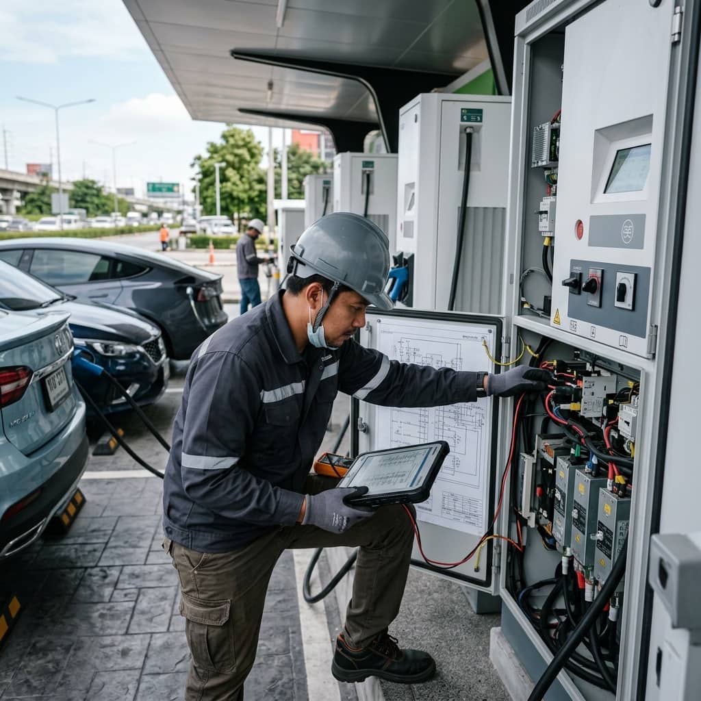
Charger maintenance involves both high-power low-voltage supply and internal capacitors. Safe procedure starts with taking the connector out of service in the management system before arriving on site, isolating at the upstream breaker with lock-out tag-out, proving dead with a proven tester before touching any termination, and, for DC units, waiting out the capacitor discharge time in the manufacturer's manual before opening power compartments. Internal work should always be performed by manufacturer-trained technicians following documented procedures.
Restoration after testing is equally ordered: torque any opened terminations to specification, close covers and check seals, energize and run one full charge test with the EVSE tester or a test vehicle, re-enable the unit in the management system, then watch its online status and the first real user session on the dashboard. The close-out report should include all measurements, before-and-after photographs, and parts replaced, keeping each unit's history complete and informing spare parts planning across the network.
- Always take the connector out of service in the system before site work
- Isolate with lock-out tag-out and prove dead before touching
- Wait out DC capacitor discharge time per the manual
- Run one full test charge before returning the unit to users
4. Faults Most Often Found in Maintenance
Field maintenance statistics repeatedly surface the same fault groups: worn or oxidized connector contacts raising contact resistance and running hot, weakened connector latch springs making the plugged state unstable, RCD trip times lengthening year over year as mechanisms age, degraded enclosure seals letting moisture reach circuit boards, and outdated firmware containing defects the manufacturer fixed long ago but that were never applied.
The improvement path is moving from corrective to condition-based maintenance, using management system data — session failure rates, RCD trip counts, internal temperature logs — to prioritize which units to inspect first. Set connector replacement criteria by mating cycle count rather than waiting for failure, and make firmware updates a standing item in every maintenance visit. This lifts network availability with the same labor hours.
Need engineering consultation regarding EV Infrastructure?
The WIN TECH SERVICE engineering team is ready to provide site surveys, electrical system inspections, and prepare accurate legal certification reports.