Installation & Safety Testing of Commercial AC Type 2 EV Chargers (7kW - 22kW)
📌 Executive Summary
Installing dedicated RCCB Type B / Type A + DC 6mA detection, dedicated MCB, and IP55 weatherproofing for fleet parking.
1. Fundamentals of 7kW - 22kW AC Type 2 Chargers
AC chargers using the Type 2 connector per IEC 62196-2 are the most widely installed category in commercial buildings and parking facilities, costing far less than DC units and suiting multi-hour dwell times. The 7.4kW size uses single-phase 32A supply, while 11kW and 22kW use three-phase 16A and 32A respectively. Designers must understand that an AC charger does not convert power itself — it is a safety controller delivering AC to the vehicle's on-board charger, so the actual charging speed is also capped by each vehicle model's on-board rating.
Sizing should follow the building's spare capacity and the typical dwell time of the user group. In an office building where staff park for eight hours, 7.4kW comfortably replenishes the daily energy needs of most vehicles, whereas fast-turnover bays or commercial fleets justify 22kW. Installing more chargers at a smaller rating combined with load management usually serves the overall user base better than a few large units within the same electrical infrastructure budget.
2. Circuit Protection to Standard
Each charger requires a dedicated branch circuit from the distribution board, comprising an MCB rated for the continuous load current and conductor size, plus residual current protection per IEC 60364-7-722: an RCD Type B, or the more cost-effective and common combination of RCD Type A with a 6mA DC residual current detector (RDC-DD). Many quality chargers integrate the RDC-DD internally, so the designer must read the unit's certification documents carefully to avoid duplicated or missing protection.
The RCD rating for personal protection is 30mA or less. Conductors should suit the real installation conditions — for example XLPE-insulated cable for outdoor conduit runs — with voltage drop calculated to remain within limits at the far end. Because EV charging is a continuous multi-hour load unlike typical receptacle loads, conductor sizing should assume full rated current continuously rather than applying ordinary demand factors. A surge protective device (SPD) at the board is also advisable where lightning exposure is significant.
- One dedicated branch circuit per charger; no shared loads
- RCD rated 30mA or less: Type B, or Type A plus 6mA RDC-DD
- Size conductors for continuous full-rated current, not ordinary demand factors
- Check whether the charger integrates an RDC-DD before choosing the RCD type
- Consider an SPD where lightning risk is significant
3. Field Installation and Environmental Protection
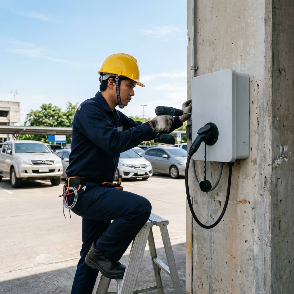
Locate the unit so the cable reaches the vehicle's charge port without crossing walkways, mount it at the ergonomic height given in the manufacturer's manual, and protect it with bollards against vehicle impact. For outdoor or open-deck installations, the charger and associated enclosures should carry at least an IP55 rating against dust and water jets, with UV-resistant materials — Thailand's sun embrittles ordinary plastics within a few years.
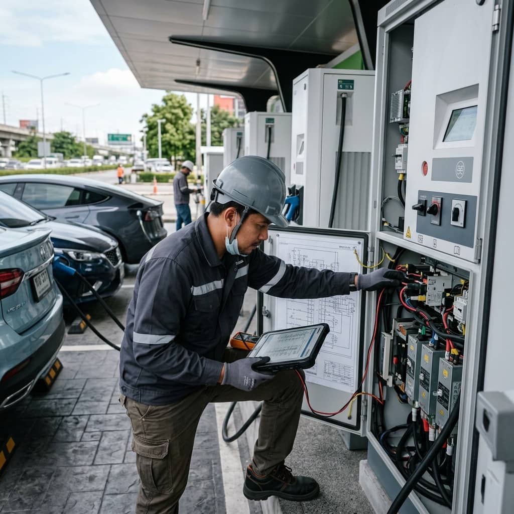
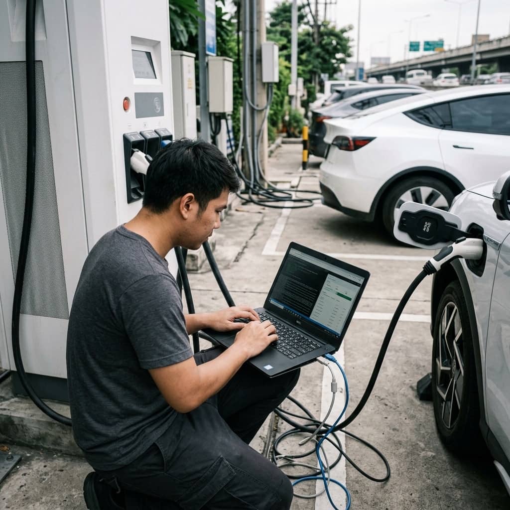
Post-installation testing proceeds in order: insulation resistance of the circuit before energization, earth continuity through to the unit, phase sequence for three-phase models, RCD verification with a proper tester, and Control Pilot testing with an EVSE simulator confirming the A-B-C state transitions and disconnection under simulated leakage and broken-earth conditions. All results should be compiled into a handover report with installation photographs, serving as reference for annual inspection and insurance purposes.
4. In-Service Problems and Maintenance
Common in-service problems include nuisance RCD tripping with no obvious cause — usually cumulative leakage from multiple vehicles on an improperly shared protective device, or moisture ingress at poorly sealed outdoor terminations. Connector and inlet wear from heavy use produces abnormal contact heating, and units may reboot spontaneously from momentary voltage dips at the far end of distribution feeders.
A recommended maintenance regime is a semi-annual to annual inspection covering RCD testing with both the test button and a trip-time meter, visual checks of connectors, cables, and flex points, torque verification of enclosure terminations to specification, thermal imaging of terminals under load, and inspection of weather seals and desiccant in enclosures. For large fleets of chargers, use management system data to identify units with abnormally high session failure rates and inspect them proactively before users complain.
- Test RCDs with both the test button and a trip-time meter
- Visually inspect connectors, cables, and flex points
- Torque terminations to specification and thermally image under load
- Check weather seals and desiccant in outdoor enclosures
Need engineering consultation regarding EV Infrastructure?
The WIN TECH SERVICE engineering team is ready to provide site surveys, electrical system inspections, and prepare accurate legal certification reports.