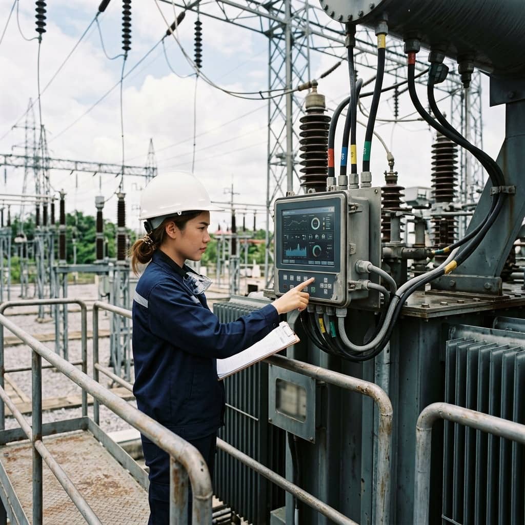
Design & Reliability of Substation Auxiliary DC & AC Power Supply Systems

📌 Executive Summary
Redundant dual battery chargers, ATS source selection, and uninterruptible distribution for critical protection circuits.
1. Auxiliary Power: The Hidden Heart of a Substation
The auxiliary power system supplies every control and protection device in a substation: protection relays, breaker trip and close coils, SCADA, communications, and emergency lighting. Its defining requirement is that it must keep working precisely when the main power system fails — a severe fault is exactly when relays and breakers demand the most energy. If the DC system fails at that moment, the entire station's protection is paralyzed. For this reason the DC system is designed to be fully independent of the primary supply, built around batteries and battery chargers.
The basic architecture is a vented lead-acid, VRLA, or nickel-cadmium battery in parallel with a float charger continuously supplying the DC load, at typical voltages of 110V or 125V DC for control and trip circuits and 48V DC for communications. Backup AC comes from two station service transformer sources through an automatic transfer switch, supplemented in critical stations by a diesel generator. Battery type selection weighs service life, ambient temperature, maintenance frequency, and battery room space together.
2. Design Standards and Battery Sizing
Substation battery sizing follows IEEE 485 for lead-acid batteries and IEEE 1115 for nickel-cadmium. The method builds a duty cycle diagram covering every load period across the required backup duration: continuous loads (relays, indication, SCADA), momentary loads (trip and close coils, spring-charging motor starts), and random loads that may occur at any time. Cell size is then calculated using capacity rating factors, multiplied by an aging factor (typically 1.25), temperature correction, and a design margin for future load growth.
For installation and maintenance, IEEE 450 provides the testing and maintenance practice for vented lead-acid batteries, and IEEE 1188 covers VRLA types. Battery room design must provide adequate ventilation to control hydrogen accumulation during charging, along with emergency eyewash provision and acid-resistant flooring per safety requirements. The DC circuits also require ground detection, because substation DC systems are operated unearthed: a first ground fault does not disable the system, but a second one can cause unintended breaker tripping.
- IEEE 485: lead-acid battery sizing for substations
- IEEE 1115: nickel-cadmium battery sizing
- IEEE 450 / IEEE 1188: maintenance and testing for VLA / VRLA batteries
- Aging factor of 1.25 and temperature correction in sizing
- Unearthed DC systems always require ground detection
3. Capacity Testing and Periodic Maintenance
The most important battery test is the capacity discharge test — the only method that proves real capacity. A load bank discharges the battery at a specified constant current while per-cell voltages are logged until the end voltage is reached, and capacity is calculated as a percentage of rating following IEEE 450 practice. When capacity falls below 80 percent of rating, the battery is considered at end of life and replacement should be planned. During the test, contingency measures — a temporary battery or work sequencing — must keep DC available to the protection system at all times.
Periodic maintenance includes monthly checks: overall and per-cell float voltages, electrolyte level and specific gravity (for vented types), terminal corrosion, and connection torque. Annual work adds connection resistance measurement and internal ohmic readings to trend the deterioration of individual cells. On the charger side, float and equalize voltages must be verified, alarms tested — low/high voltage, DC ground, charger fail — and the AC source transfer switch exercised to confirm it operates as designed.
- A load bank capacity test is the only true proof of capacity
- Below 80% of rated capacity, plan battery replacement
- Routinely check per-cell float voltages and connections
- Test charger alarms and AC source transfer operation
4. Common Failure Modes and Designing for Reliability
Frequent DC system failures include a single deteriorated cell dragging down the whole string under heavy load, loose or corroded connections causing excessive voltage drop during breaker tripping, chargers set to the wrong float voltage leading to premature aging or chronic undercharge, and accumulated double DC grounds causing false trips. Most of these are detectable in advance through disciplined periodic maintenance — the weakness is that DC systems work silently in the background and are easily neglected until the day they are truly needed.
High-reliability designs for critical stations use dual battery banks with independent chargers feeding two DC buses, separating the trip supplies of Main 1 and Main 2 protection so no single failure disables all protection. DC distribution should coordinate fuses and miniature breakers for selectivity, isolating a faulted circuit without affecting others, and a continuous battery monitoring system measuring per-cell voltage, temperature, and current — reported to SCADA — reveals deterioration trends before they become failures.
Need engineering consultation regarding Substation & Automation?
The WIN TECH SERVICE engineering team is ready to provide site surveys, electrical system inspections, and prepare accurate legal certification reports.