Ring Main Unit (RMU) Automation for Smart Distribution Grids
📌 Executive Summary
Motorized RMU actuators, Fault Passage Indicators (FPI), and RTU telecontrol for rapid feeder self-healing and restoration.
1. The RMU's New Role in Smart Distribution Networks
A Ring Main Unit (RMU) is a sealed medium-voltage switchgear assembly widely used in ring (loop) distribution networks of utilities and industrial plants. It typically comprises two load break switches for the incoming and outgoing ring cables plus a transformer protection way — either switch-fuse or circuit breaker. Internal insulation is commonly SF6 gas, with solid or air insulation technologies gaining ground in newer designs for environmental reasons. The ring topology's strength is that when any cable section faults, the damaged section can be isolated and supply restored from the other side of the ring, keeping the outage area small.
The problem is that conventional RMUs are entirely manual: after a fault, crews must drive from unit to unit locating the damage and switching by hand, taking hours. RMU automation — adding motorized actuators, Fault Passage Indicators (FPI), a Remote Terminal Unit (RTU), and communications — gives the control centre immediate visibility and remote switching, and with automation logic the network can isolate faults and restore supply by itself within minutes or seconds. This directly improves reliability indices such as SAIDI and SAIFI.
2. Equipment Standards and FLISR Architecture
The RMU switchgear itself must comply with the IEC 62271 series — notably IEC 62271-200 for metal-enclosed medium-voltage switchgear, covering short-circuit withstand and Internal Arc Classification (IAC) for personnel protection, and IEC 62271-103 for load break switches. RTUs and control-centre communication typically use IEC 60870-5-104 or DNP3 over cellular, fiber, or radio networks. The control cabinet's battery-backed supply must be designed to operate through local outages, since that is precisely when the automation is needed.
The automation architecture, collectively called FLISR (Fault Location, Isolation and Service Restoration), takes three main forms: centralized, with logic in the control centre's DMS/ADMS, suited to large networks needing a global view; decentralized, where field RTUs decide cooperatively via peer-to-peer communication for faster response; and local, where each device acts on its own logic, such as sectionalizers counting recloser operations. The choice depends on communication infrastructure, budget, and each utility's operating philosophy.
- IEC 62271-200: metal-enclosed switchgear and Internal Arc Classification
- IEC 62271-103: medium-voltage load break switches
- IEC 60870-5-104 / DNP3: control-centre communication protocols
- FLISR: centralized, decentralized, and local logic schemes
3. Retrofitting Existing RMUs for Automation
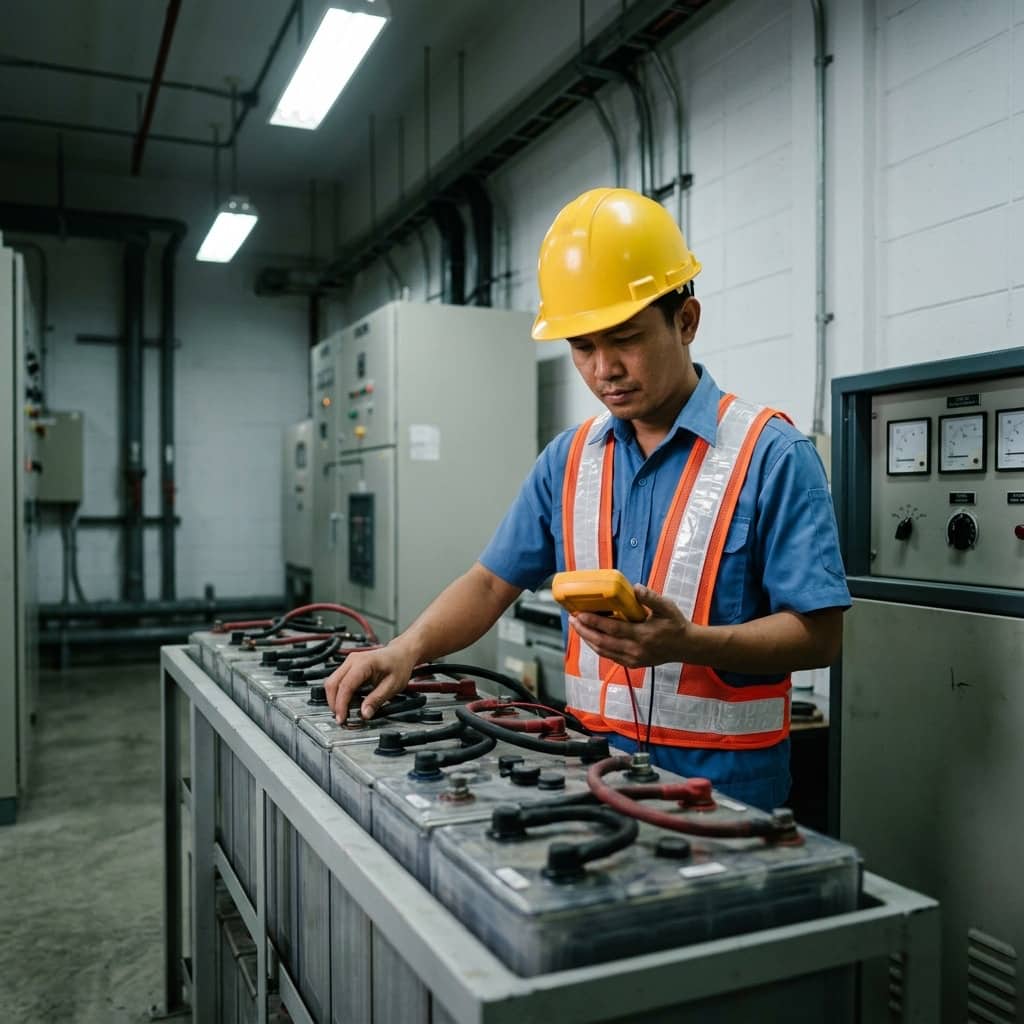
Retrofitting in-service RMUs starts with a readiness survey: the model and condition of the switch mechanism, actuator compatibility with the existing mechanism, space for the RTU control cabinet, battery and LVAC supply condition, and actual communication signal quality on site. Very old units, or those without manufacturer-supported actuators, may be better replaced outright with factory automation-ready RMUs. Deployment should be prioritized by reliability benefit, typically starting at ring mid-points and tie points between feeders.
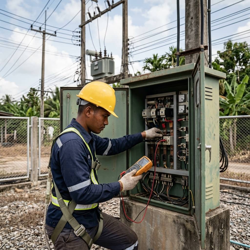
Pre-commissioning tests cover full open-close cycling of motorized actuators, FPI verification by injecting simulated fault current through the CTs, point-to-point testing of every signal on the signal list against the control centre, and end-to-end FLISR logic testing with simulated faults on each cable section to confirm switching sequence, interlocks, and total restoration time. It is good practice to run initially in monitoring mode — the system recommends switching actions but a human confirms — before enabling fully automatic operation once the logic has proven itself.
- Always verify actuator compatibility with the existing mechanism first
- Deploy first at ring mid-points and feeder tie points
- Test FPIs by injecting simulated fault current
- Run end-to-end FLISR logic tests for every fault scenario
- Operate in monitoring mode before full automatic mode
4. Common Field Problems and Remedies
Common problems after commissioning include FPI false indications from pickup settings unsuited to actual load or from inrush current during restoration — leading FLISR to mislocate faults; control-cabinet batteries failing silently so the RTU dies exactly when the local supply does; and intermittent communication dropouts in weak cellular coverage areas, eroding the control centre's trust in the whole system. Heat and humidity in outdoor control cabinets are also a frequent cause of electronics degradation in tropical climates.
Prevention means tuning FPI settings from each feeder's real load data and enabling time-delay or inrush-detection features where available; scheduling routine battery tests and remote switching exercises to confirm readiness at every point; deploying communication health monitoring with alarms for prolonged dropouts; and designing cabinets with ventilation and moisture protection appropriate to site conditions. Critically, FLISR logic must be reviewed whenever the ring topology changes — a new tie point, or the connection of distributed generation.
Need engineering consultation regarding Substation & Automation?
The WIN TECH SERVICE engineering team is ready to provide site surveys, electrical system inspections, and prepare accurate legal certification reports.