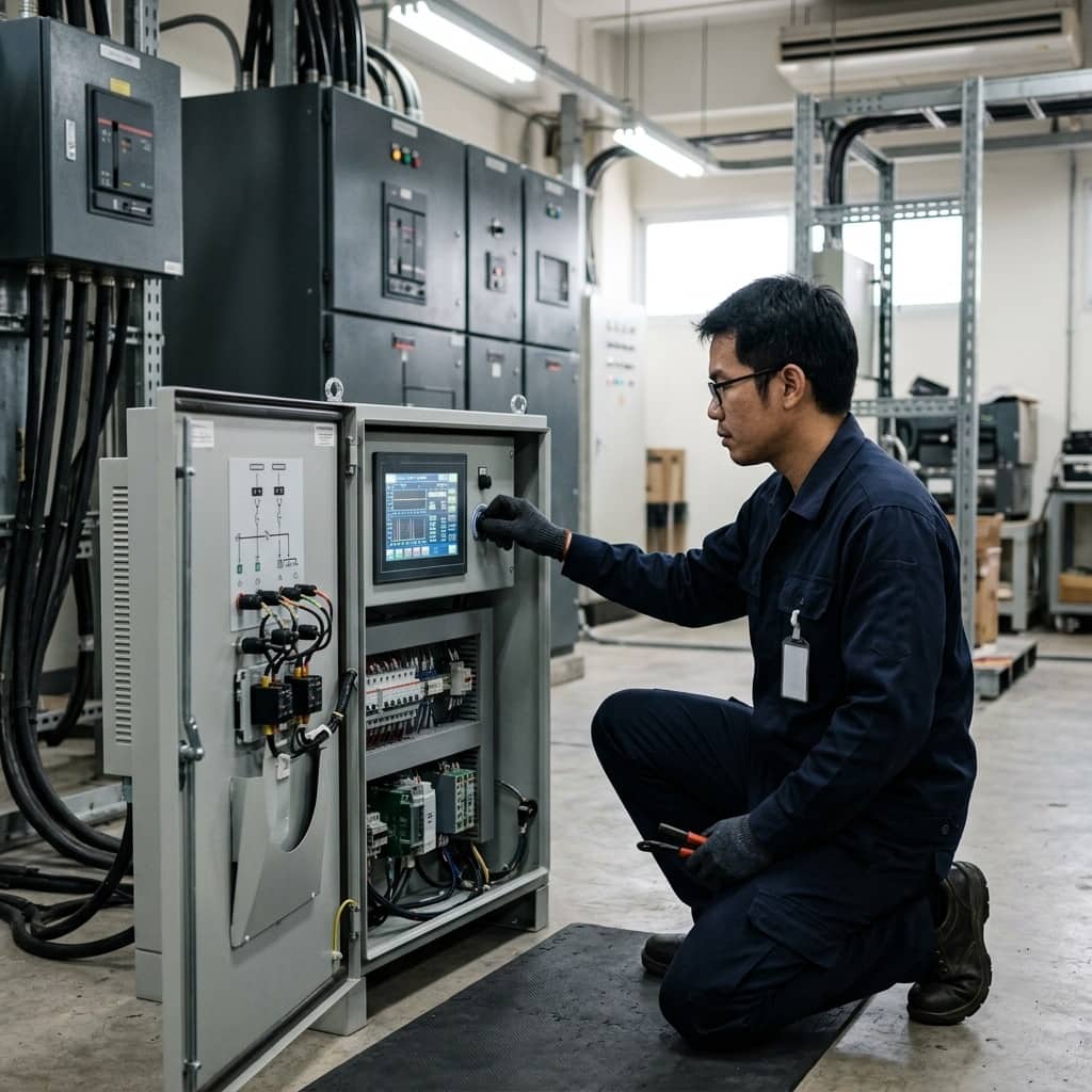
Selecting K-Factor Rated Transformers for Non-Linear Industrial Loads

📌 Executive Summary
Determining K-4, K-13, and K-20 transformer ratings to withstand severe eddy current and stray load losses from non-linear power supplies.
1. How Non-Linear Loads Stress Transformers
Transformers are designed on the assumption of sinusoidal load current at fundamental frequency, but modern loads such as VFDs, chargers, servers, and LED lighting draw current rich in harmonics. Harmonic currents create excess heat through two main mechanisms: winding eddy current loss, which rises roughly with the square of the harmonic order, and other stray losses in structural metalwork. The result is a transformer that overheats and ages its insulation prematurely even while loaded below its nameplate rating.
Field symptoms include abnormally high transformer temperature at only about half rated current, the smell of hot insulation, and in three-phase four-wire systems, high neutral current from triplen harmonics that add instead of cancelling. Engineers therefore need a finer tool than the plain kVA rating to assess transformers feeding electronic loads, which is where the K-Factor concept comes in.
2. K-Factor and the Related Standards Landscape
K-Factor is an index per UL 1561 practice that weights each harmonic current by the square of its order, reflecting its contribution to winding eddy current loss. Transformers rated K-4, K-13, or K-20 are built to absorb the heating of loads with that level of harmonic content without exceeding insulation temperature limits. IEEE guidance documents cover evaluating the non-linear load capability of existing transformers, while European practice uses Factor K per IEC/EN methods, calculated differently but addressing the same problem.
A crucial point is that a high K rating does not mean the transformer filters harmonics; a K-rated unit merely tolerates the heat, and harmonic currents still flow upstream to disturb the system. Actual harmonic reduction requires filters or phase-shifting transformers. An isolation transformer with an electrostatic shield between primary and secondary windings adds further benefits: attenuating common mode noise and establishing a fresh ground reference for sensitive loads.
- K-Factor per UL 1561 weights harmonics by the square of their order
- Europe uses Factor K per IEC/EN methods for the same problem
- K-rated transformers tolerate heat but do not filter harmonics
- An electrostatic shield attenuates common mode noise
3. Calculating K-Factor from Actual Measurements
Selecting the right K rating starts with measuring the current spectrum of the actual load, or the closest comparable one, using an analyzer that reads individual harmonics to at least the 25th order. K-Factor is then computed as the sum of each order's per-unit current squared times the order squared. Measurement should capture the periods of heaviest electronic load and span multiple intervals to see the distribution, never relying on a single snapshot.
For new projects with no load yet available, K can be estimated from typical spectra of each load type weighted by its share of the circuit; predominantly computer and office equipment circuits are commonly specified K-13, while general mixed circuits with some electronics may need only K-4. Over-specifying inflates transformer cost and size with no added benefit, so the decision should use the best available data with a reasoned allowance for future changes in the load mix.
4. Design Alternatives and Mistakes to Avoid
A K-rated transformer is not the only answer. A widely used alternative is derating a standard transformer, selecting a larger unit run below nameplate, which can be more economical if calculated properly from that model's loss data. Another route is treating harmonics at the source with filters, allowing standard transformers while reducing system-wide impact. In four-wire systems with high triplen content, transformer neutral terminals and feeder neutrals should be sized at twice the phase conductor per accepted practice.
Mistakes to avoid include buying a high-K unit without ever measuring the load, believing K-rating reduces system THD, neglecting neutral current until the neutral termination overheats, and installing an isolation transformer without earthing its electrostatic shield, which eliminates its noise rejection entirely. Every project should close with temperature and current spectrum measurements under real load to confirm the rating choice matches the analysis.
- Compare options: K-rated, derated standard unit, or source filtering
- Size neutrals at twice the phase conductor in four-wire systems
- Always earth the isolation transformer's electrostatic shield
- Verify with temperature and spectrum measurements under real load
Need engineering consultation regarding Power Quality & Energy?
The WIN TECH SERVICE engineering team is ready to provide site surveys, electrical system inspections, and prepare accurate legal certification reports.