Digital Twin Applications in Factory Power Distribution Networks
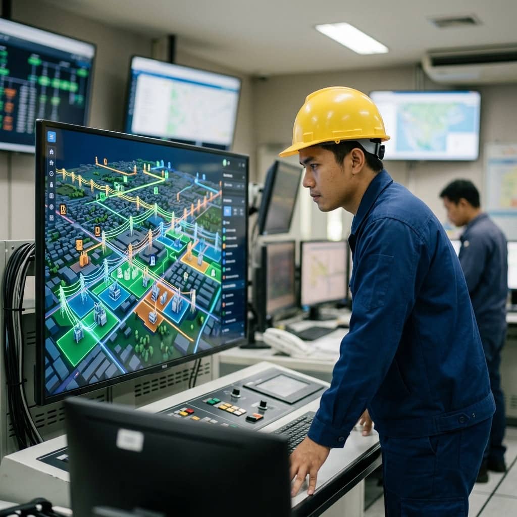
📌 Executive Summary
Using real-time simulation models to predict load flow, transient stability, harmonic propagation, and optimal maintenance scheduling.
1. What a Digital Twin Means for Factory Power Systems
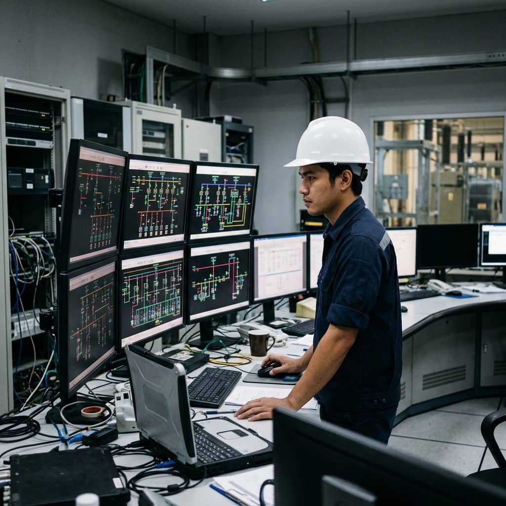
In the context of factory power distribution, a digital twin is a digital model of the electrical system continuously linked to live field data. Unlike a conventional study model — a load-flow model built once at design time — a digital twin is kept aligned with reality through data from meters, relays, and sensors via SCADA or a power monitoring system, so the model reflects both the current network state (breaker positions, transformer tap positions) and actual hourly load behaviour.
The core value is turning "what if" questions into answers obtained before acting: what happens to voltage drop and transformer spare capacity if a new machine is added to this feeder; can the remaining system carry the load if one transformer is taken out for maintenance; what fault current and protection sequence follows a short circuit at a given bus. Simulating on a model that matches reality concretely reduces the risk of operational and investment decisions — especially in factories whose systems grow more complex with rooftop solar and energy storage.
- Simulate impact before adding loads or new machinery
- Check N-1 security before removing equipment for maintenance
- Analyze fault currents and protection operating sequences
- Assess the impact of rooftop solar and energy storage
2. System Building Blocks and Relevant Standards
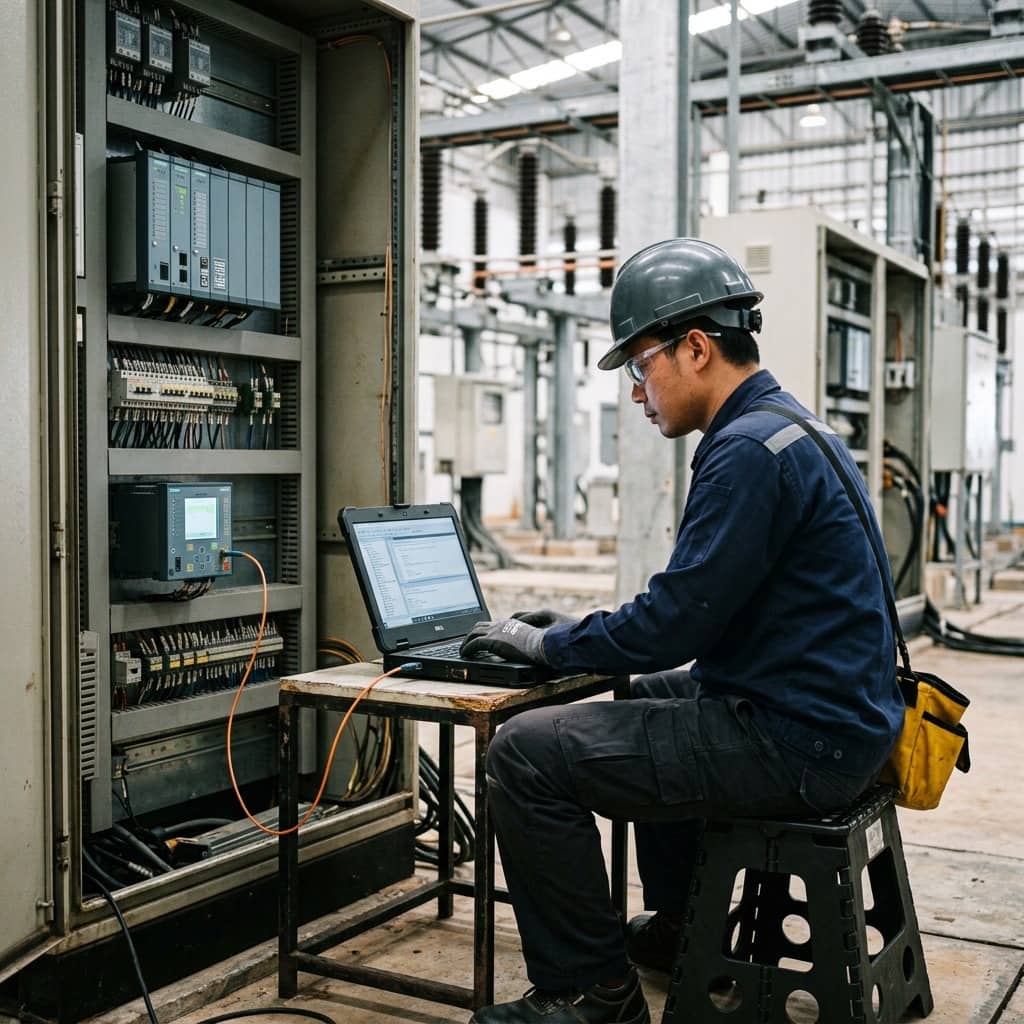
An electrical digital twin has three main layers. First, the network model containing impedances of cables, transformers, and all equipment, with a single line diagram matching the field. Second, the data layer collecting measurements from meters and relays over standard protocols — Modbus, IEC 61850 MMS, or OPC UA — into a time-series database. Third, the analytics engine running load flow, short circuit, and harmonic calculations on current data, using standardized methods such as IEC 60909 for short-circuit current calculation.
For data structure, the power industry has the Common Information Model (CIM) of the IEC 61970/61968 series for exchanging network models between different vendors' software, reducing long-term vendor lock-in. Power quality assessment within the model references accepted criteria such as IEEE 519 for harmonic limits. Importantly, a digital twin need not start as a full-scale system: many factories begin with a model calibrated against monthly meter data, then raise data frequency and automation as readiness grows.
- IEC 60909: short-circuit current calculation method
- IEC 61970/61968 (CIM): network model data structure
- IEEE 519: harmonic limits in power systems
- Modbus / IEC 61850 / OPC UA: data acquisition protocols
3. Building and Calibrating the Model
Building the twin starts with assembling complete, accurate system data: the latest single line diagram, transformer and generator nameplates, cable types, sizes, and lengths for every section, protection settings, and metered load data. This stage frequently reveals that site documentation does not match reality — a hidden benefit of the project, since it forces as-built verification and drawing updates. The data is then entered into power system analysis software and connected to the data layer from the power monitoring system.
What makes the model trustworthy is calibration: comparing calculated results against real measurements under known conditions — calculated versus measured voltage at main buses at peak and minimum load, and power flows on each feeder against meter readings. Deviations beyond tolerance must be traced to causes, commonly wrong cable impedance data, incorrect CT/PT ratios, or unmetered hidden loads. Calibration should be repeated periodically, and a change-management process must update the model whenever the real system changes — otherwise the twin rapidly degrades into just another document that no longer matches reality.
4. Practical Use, Limitations, and a Sensible Starting Point
High-return factory applications include planning for new loads without unnecessary equipment oversizing, re-verifying protection coordination whenever the system changes, switching studies before major maintenance, and post-event root cause analysis by replaying disturbances on the model. An arc flash model linked to the current network structure also keeps safety labels and PPE selection aligned with actual conditions at all times.
The limitation to accept is that a digital twin carries ongoing ownership costs: software, staff who understand both power systems and data systems, and the discipline to keep the model current. Organizations that fail with digital twins rarely fail on technology — they fail on data stewardship after project handover. A sensible start is to define one or two concrete use cases, such as transformer spare capacity management, build and prove the model within that scope, then expand step by step — with a clearly named model owner accountable for data accuracy from day one.
Need engineering consultation regarding Substation & Automation?
The WIN TECH SERVICE engineering team is ready to provide site surveys, electrical system inspections, and prepare accurate legal certification reports.